MCHP Comparator / Op-Amp / Voltage Reference


When to use:
When to use:
- Legacy dsPIC30F or dsPIC33FJ target device (DS70357 & DS70648 datasheets)
- Older project maintenance or existing design migration
- Internal CVR voltage reference needed (16-level programmable reference)
- Op-amp functionality available on device (unity gain, non-inverting, inverting)
- Comparator with digital filtering or blanking logic required
When NOT to use:
- Newer dsPIC33E/C/A device — use High-Speed Analog Comparator block instead
- Sub-microsecond response time needed — legacy comparator slower than HS version
- Slope compensation required — use High-Speed Analog Comparator w/ Slope block
- PGA functionality needed — use dedicated PGA block (dsPIC33C/A)
Overview
The MCHP Comparator / Op-Amp / Voltage Reference block provides access to the analog comparator, operational amplifier, and voltage reference (CVR) modules found in legacy dsPIC30F and dsPIC33FJ devices (DS70357 & DS70648). This block combines configuration for all three analog functions in a single interface.
Key Features:
- Multiple comparator instances (device-dependent)
- Comparator voltage reference (CVR) module
- Op-amp functionality (device-dependent)
- Configurable interrupt and event generation
- Digital filtering and blanking support
- Pin mapping for analog inputs and outputs
Typical Applications
- Signal Conditioning: Op-amp gain stages for sensor interfaces
- Threshold Detection: Comparator-based limit detection
- Reference Generation: CVR module for DAC functionality
- Motor Control: Current and voltage sensing
- Power Management: Supply voltage monitoring
Block Dialog
The Comparator / Op-Amps / Voltage Reference block opens its custom configuration window (not the Simulink mask) when double-clicked:
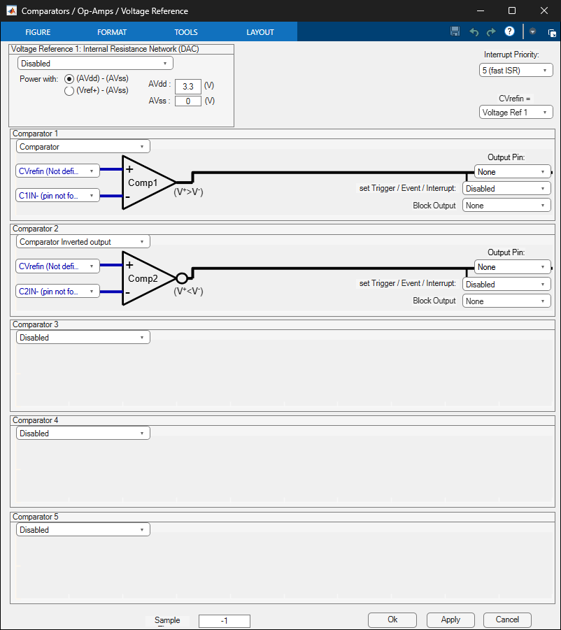
Screenshots taken with chip 33EP64GS808
The window groups settings by physical peripheral:
- Voltage Reference 1 — internal resistance-network DAC; choose the
AVdd / AVssorVref+ / Vref-power rail, enter the analog rail voltages, and optionally route the reference to theCVref1Opin. - Interrupt Priority — shared ISR priority for all comparators on the page.
- Comparator 1 / 2 / 3 (and more on chips with additional analog comparators) — one pane per comparator. Each pane’s drop-down is disabled by default; enabling it exposes the comparator’s input-muxing, hysteresis, filtering and output-polarity parameters.
- Sample Time — block sample time for any block-level output (status pins, interrupt-triggered subsystem call).
-1by default.
Parameters
Function Tab
Comparator/Op-Amp Configuration
Each comparator/op-amp instance can be independently configured:
| Parameter | Description | Options |
|---|---|---|
| CON (Comparator Mode) | Operating mode selection | Off, Comparator, Op-Amp |
| OPMODE (Op-Amp Mode) | Op-amp configuration | Unity Gain, Non-Inverting, Inverting (device-dependent) |
| CPOL (Comparator Polarity) | Output polarity | Normal, Inverted |
CVR Module Configuration
| Parameter | Description | Range |
|---|---|---|
| CVR1OE | CVR1 output enable | On, Off |
| CVR2OE | CVR2 output enable | On, Off |
| VREFSEL | Voltage reference source | Internal, External |
| RLadder | Resistor ladder tap selection | 0-15 (16 levels) |
| AVdd | Positive supply voltage | Voltage value |
| AVss | Negative supply voltage | Voltage value |
| CVRSS | CVR range selection | Low (0 to VDD/4), High (VDD/4 to VDD) |
Pins Configuration Tab
Input/Output Pin Mapping
| Parameter | Description | Options |
|---|---|---|
| OutputPort_COE_RP | Comparator output pin assignment | Pin list or “None” |
| InputP_CREF | Positive input selection | Internal CVR, External pins |
| InputN_CCH | Negative input selection | External pins, Internal reference |
Event and Interrupt Configuration
| Parameter | Description | Options |
|---|---|---|
| Trigger_EventInterrupt_EVPOL | Event trigger polarity | Disabled, Rising edge, Falling edge, Both edges |
| BlockOutputEvent | Enable event output port | Enabled, Disabled |
| BlockOutputState | Enable state output port | Enabled, Disabled |
| IntPriority | Interrupt priority level | 0-7 |
Advanced Filtering
| Parameter | Description | Range |
|---|---|---|
| FilterFreq | Digital filter cutoff frequency | 10 Hz to 10 GHz |
| Blanking | Enable blanking functionality | Enabled, Disabled |
| BlankingSignal | Blanking source signals | Signal list |
| BlankingTruthTable | Logic table for blanking conditions | Truth table matrix |
Block Outputs
| Port | Description | Data Type |
|---|---|---|
| Event Optional | Comparator event output | Boolean (per instance) |
| State Optional | Current comparator state | Boolean (per instance) |
Note: Output ports are dynamically created based on BlockOutputEvent and BlockOutputState settings.
Notes
Legacy Device Support
This block is designed for legacy dsPIC30F and dsPIC33FJ devices. For newer devices:
- dsPIC33E/EP/EV: Use “High-Speed Analog Comparator” block
- dsPIC33C/CK/CH: Use “High-Speed Analog Comparator” block
- dsPIC33A: Use “High-Speed Analog Comparator” and “Op-Amp” blocks
Pin Availability
Available pins vary significantly by device package and configuration. The MCHP Master block detects available pins based on:
- Selected device
- Enabled peripherals
- Pin remapping (PPS) configuration
CVR Voltage Calculation
CVR output voltage depends on:
- CVRSS range selection
- RLadder tap selection
- Supply voltage (AVdd, AVss)
Formula:
- Low range: VCVR = (RLadder/24) × AVdd
- High range: VCVR = (AVdd/4) + (RLadder/32) × (3AVdd/4)
Filter and Blanking
Digital filtering and blanking features provide noise immunity:
- FilterFreq: Sets low-pass filter cutoff
- Blanking: Masks comparator output during specified conditions
- BlankingTruthTable: Defines complex blanking logic
Device Support
dsPIC30F Series
- Comparator modules: 1-5 (device-dependent)
- CVR module with 16 voltage levels
- Op-amp functionality (select devices)
dsPIC33FJ Series
- Comparator modules: 1-5 (device-dependent)
- CVR module with programmable output
- Enhanced filtering and blanking
Note: Newer dsPIC33E/C/A devices use separate dedicated blocks:
- Use High-Speed Analog Comparator block for dsPIC33E/C/A
- Use Op-Amp block for dsPIC33C/A devices
- Use PGA block for programmable gain amplifiers
Examples
Basic Comparator with Internal Reference
1. Set CON = "Comparator" for desired instance
2. Configure CREF (positive input) to internal CVR
3. Set RLadder to desired voltage level
4. Configure CCH (negative input) to external pin
5. Enable OutputPort_COE_RP for digital output
Op-Amp Configuration
1. Set CON = "Op-Amp" for desired instance
2. Select OPMODE (Unity Gain, Non-Inverting, etc.)
3. Map input pins appropriately
4. Verify device supports selected op-amp mode
CVR Module as DAC
1. Enable CVR1OE or CVR2OE
2. Set VREFSEL and CVRSS for range
3. Program RLadder for desired voltage
4. Output appears on CVR output pin
References
- dsPIC30F Family Reference Manual — Comparator Module (DS70046E)
- dsPIC33F Family Reference Manual - Comparator with CVR
- Application Note AN1137: Analog Comparator Applications
Related Blocks
- High-Speed Analog Comparator: For dsPIC33E/C/A devices
- High-Speed Analog Comparator with Slope: Enhanced slope compensation
- Op-Amp: Dedicated op-amp block for dsPIC33C/A
- PGA: Programmable Gain Amplifier for dsPIC33A
- ADC: Analog-to-Digital Converter blocks