CN - Change Notification (Pin Interrupt)


Block Dialog
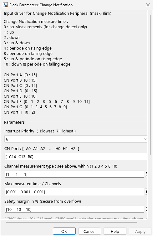
Screenshots taken with chip 33AK512MPS512
Overview
The MCHP_CN block provides an interface to the Change Notification (CN) peripheral, which detects pin state changes and measures transition timing. While primarily used for GPIO interrupts (buttons, switches), CN can also serve as a simple encoder interface or pulse counter.
When to use:
- Button/switch inputs — Detect button presses, switch changes, or external events
- Pulse timing — Measure pulse width, period, or frequency of external signals
- Simple encoders — Low-speed rotary encoders without dedicated QEI hardware
- Wake-from-sleep — Pin change interrupts can wake MCU from low-power mode
- Multi-pin monitoring — Detect changes on multiple GPIO pins simultaneously
When NOT to use:
- High-speed encoders — Use QEI or QDEC blocks (hardware decoding faster/more reliable)
- Motor control encoders — Use QEI/QDEC/PDEC for accurate position/velocity (CN may miss edges)
- SPI/I2C/UART/CAN — Use protocol-specific blocks (not GPIO bit-level)
- Continuous polling — If reading pin every cycle, use Digital Input block instead
- Very high frequency — CN interrupt overhead limits max pulse rate (~100 kHz) Key Features:
- Multi-pin state change detection (up to 32 CN pins)
- Edge detection: rising, falling, or both
- Transition timing measurement (time between edges)
- Period measurement (rising-to-rising or falling-to-falling)
- Programmable pull-up/pull-down resistors
- Interrupt generation on pin change
- Wake from sleep on pin change
- Can be used for simple rotary encoders or pulse counting
Device Support
| Family | CN Type | CN Pins | Notes |
|---|---|---|---|
| dsPIC30F | Type 0 | CN0-CN15 | Dedicated CN peripheral |
| dsPIC33F | Type 0 | CN0-CN23 | Dedicated CN peripheral |
| dsPIC33E | Type 1 | All GPIO pins | All ports have CN capability |
| dsPIC33C | Type 1 | All GPIO pins | All ports have CN capability |
| dsPIC33A | Type 1 + SCCP | All GPIO pins | All ports; timing timer width selectable (16-bit or 32-bit SCCP) |
| PIC32MK | Type 2 | Port-based | One interrupt per port |
Parameters
Channel Selection
| Parameter | Description |
|---|---|
| CN Channels (dsPIC30F/33F) | Vector of CN channel numbers, e.g., [0 1 2] for CN0, CN1, CN2 |
| CN Port (dsPIC33E/C, PIC32MK) | Port pin list, e.g., A0 A1 B5 for PA0, PA1, PB5 |
Measurement Configuration (per channel)
| Mode Value | Measurement | Output Ports |
|---|---|---|
| 0 | Change detect only | Change detected flag only |
| 1 | Measure time UP (rising edge to falling edge) | T_Up (pulse width high) |
| 2 | Measure time DOWN (falling edge to rising edge) | T_Down (pulse width low) |
| 3 | Measure UP & DOWN | T_Up, T_Down |
| 4 | Period on rising edge | P_Rising (time between rising edges) |
| 8 | Period on falling edge | P_Falling (time between falling edges) |
| 5 | UP + Period on rising | T_Up, P_Rising |
| 10 | DOWN + Period on falling | T_Down, P_Falling |
Change Detection (per channel)
| Value | Detection Mode | Output |
|---|---|---|
| 0 | No change detection | - |
| 1 | Rising edge | CNx_Rise (timestamp) |
| 2 | Falling edge | CNx_Fall (timestamp) |
| 3 | Both edges | CNx_Rise&Fall (timestamp) |
Advanced Configuration
| Parameter | Description |
|---|---|
| Output Port Value | Enable current pin state output (boolean per channel) |
| Max Channel | Maximum expected time for measurements (seconds, per channel) |
| Safe Margin | Percentage margin for timer overflow protection (per channel) |
| Interrupt Priority | CN interrupt priority level (1-7) |
Timer Bit Width (TimerBitWidth) | dsPIC33A only — Selects the width of the SCCP timer used for CN timestamping: 16 bits (default — covers up to 65 536 counts per timer tick, lower RAM footprint) or 32 bits (uses one full 32-bit SCCP module, max count = 4 294 967 296 — removes overflow concerns for long pulses, at the cost of one SCCP resource). The output port datatype follows the selection (uint16 for 16-bit, uint32 for 32-bit). On all other families the field is hidden and fixed at 16 bits. |
dsPIC33A 32-bit SCCP mode — When Timer Bit Width = 32 bits, the block allocates a 32-bit SCCP timer from the device pool. If the timer pool reports no available 32-bit width (e.g. all SCCPs already taken by other peripherals), the callback falls back to 16-bit and emits the warning
MCHP:CN32bit. Check Timer Info block output to audit SCCP usage.
CN Peripheral Registers
dsPIC30F/33F (Type 0)
// Enable CN module CNCONbits.ON = 1; // Enable specific CN pins CNEN1bits.CN0IE = 1; // Enable CN0 CNEN1bits.CN1IE = 1; // Enable CN1// Enable pull-ups CNPU1bits.CN0PUE = 1; // Pull-up on CN0// Interrupt configuration IFS1bits.CNIF = 0; // Clear interrupt flag IEC1bits.CNIE = 1; // Enable CN interrupt IPC4bits.CNIP = 5; // Priority level// Read current state state = PORTBbits.RB0; // Read pin state (if CN0 is on RB0)
dsPIC33E/33C (Type 1)
// All GPIO pins have CN capability// Enable change notification on specific pins// For port A, pin 0 (PA0/RA0): CNENAbits.CNIEA0 = 1; // Enable CN on RA0 CNPUAbits.CNPUA0 = 1; // Pull-up on RA0// Interrupt per port IFS3bits.CNAIF = 0; // Clear Port A CN interrupt IEC3bits.CNAIE = 1; // Enable Port A CN interrupt
PIC32MK (Type 2)
// One CN interrupt per port CNENAbits.CNIEA0 = 1; // Enable CN on RA0// Edge select (positive/negative/both) CNNEAbits.CNNEA0 = 0; // 0 = positive edge, 1 = negative edge// Interrupt control IFS3bits.CNAIF = 0; IEC3bits.CNAIE = 1;
Output Scaling
Workspace Variables
The block creates workspace variables for scaling calculations:
| Variable | Description |
|---|---|
CN0max, CN1max, … | Maximum timer count per CN channel |
Scaling Formula
Output values are in raw timer ticks. To convert to physical time:
Time_Resolution = Max_Channel / CNxmax
Time_seconds = Timer_Ticks × Time_Resolution
Example: With CN0max = 65535 and Max_Channel = 0.1s:
Time_Resolution = 0.1 / 65535;        % ≈ 1.53 µs per tick
Pulse_Width_s = CN0_Up * Time_Resolution;
Period_s = CN0_Per * Time_Resolution;
Frequency_Hz = 1 / Period_s;
Performance Considerations
Timing Resolution
// Timer resolution depends on Max_Channel and timer selection// Block automatically chooses best timer to meet requirements// Example: Max_Channel = 1ms, CNxmax = 65535 Time_Resolution = 1e-3 / 65535 = 15.3 ns; // For pulse width measurement accuracy:// ±1 count error = ±15.3 ns// For longer periods, resolution decreases:// Max_Channel = 1s → Resolution = 15.3 µs
Interrupt Overhead
Typical CN Interrupt Overhead:
- Interrupt latency: 10-20 instruction cycles
- Handler execution: 50-100 cycles (depends on measurements enabled)
- At 70 MIPS: ~1-2 µs total per CN event
- For high-frequency signals (>100 kHz), consider Input Capture or QEI
Examples
Example 1: Button Interface with Debouncing
Application: 4-Button User Interface
Hardware: 4 push buttons on CN0-CN3 with pull-ups
Configuration:
- Channels: [0 1 2 3]
- Measurement: [0 0 0 0] (change detect only)
- Change Detection: [1 1 1 1] (rising edge = button press)
- Output Port Value: [1 1 1 1] (read button state)
Example 2: Rotary Encoder (Simple, No Quadrature Decoding)
Application: Rotary Switch Position Detection
Hardware: Mechanical rotary encoder on CN0 (A) and CN1 (B)
Configuration:
- Channels: [0 1]
- Measurement: [0 0]
- Change Detection: [3 3] (both edges)
Example 3: Pulse Width and Period Measurement
Application: External PWM Signal Analysis
Configuration:
- Channels: [0]
- Measurement: [5] (UP + Period on rising)
- Max Channel: [0.1] (100 ms max) // Measure external PWM duty cycle and frequency Pulse_Width_High = CN0_Up; // Time high (timer counts) Period = CN0_Per; // Time between rising edges// Convert to physical units (CNxmax variable set by block) Time_Resolution = Max_Channel / CN0max; Pulse_Width_seconds = Pulse_Width_High * Time_Resolution; Period_seconds = Period * Time_Resolution; // Calculate duty cycle and frequency Duty_Cycle_percent = (Pulse_Width_seconds / Period_seconds) * 100; Frequency_Hz = 1 / Period_seconds; // Example: CN0max=65535, Max_Channel=0.1s// Resolution = 0.1/65535 = 1.53 µs// If CN0_Up=32768, Pulse_High=50ms// If CN0_Per=65535, Period=100ms → 10 Hz, 50% duty
Example 4: Wake from Sleep on Button Press
Application: Low-Power Wakeup
Configuration:
- Channels: [0] (wakeup button)
- Change Detection: [1] (rising edge)
- Enable pull-down (button connects to VDD)
Troubleshooting
Issue: Multiple False Triggers (Button Bounce)
Cause: Mechanical switch contacts bounce
Solutions:
- Implement software debouncing (ignore edges for 10-50ms after first edge)
- Add external RC filter (e.g., 10kΩ + 100nF)
- Use hardware Schmitt trigger inputs
Issue: Missed Events at High Frequency
Cause: CN interrupt rate too high or interrupt latency
Solutions:
- Use dedicated counter peripheral (QEI, Input Capture) for high-speed signals
- Increase interrupt priority
- Reduce other interrupt sources
Issue: Timer Overflow (CNxmax exceeded)
Cause: Signal period exceeds Max Channel setting
Solutions:
- Increase “Max Channel” parameter
- Increase “Safe Margin” for more headroom
- Use larger timer prescaler (block automatically selects best timer)
References
- dsPIC30F/33F Family Reference Manual - Section: Change Notification Module
- dsPIC33E/33C Family Reference Manual - Change Notice (CN) peripheral
- PIC32 Family Reference Manual - Change Notice/Interrupt-on-Change
- dsPIC33A Family Reference Manual - CN peripheral
Last Updated: 2024 | MCHP Blockset for MATLAB/Simulink