OC SW - Software Output Compare


When to use:
When to use:
- Runtime pulse updates needed (frequency, duty cycle, asymmetric timing)
- Any GPIO pin required (not limited to OC peripheral pins)
- More operational modes than OC_HW (Up/Down, Period control, Toggle)
- Flexible waveform generation with dynamic reconfiguration
- CPU overhead acceptable (interrupt per edge transition)
When NOT to use:
- High-frequency PWM required (>10 kHz) — use OC_HW for zero CPU overhead
- Motor control PWM needed — use dedicated PWM blocks (PWM_HS_FEP)
- Minimal interrupt latency critical — hardware OC has no ISR delay
- Timer resource limited — OC_SW consumes one timer per channel
Block Dialog
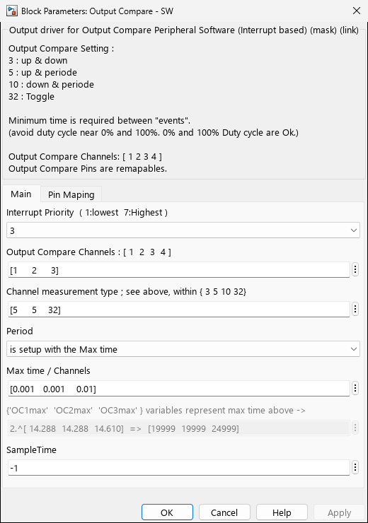
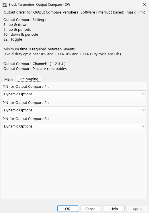
Screenshots taken with chip
33AK512MPS512Overview
The MCHP_OC_SW block provides interrupt-driven software output compare functionality. Unlike hardware OC which operates autonomously, this block uses timer interrupts to precisely time output pin changes, offering greater flexibility at the cost of CPU overhead.
Parameters
Channel Configuration
| Parameter | Description | Values |
|---|---|---|
| Channel | OC channel identifiers to use | 1-9 (logical channels, not hardware OC) |
| Channel_UP_Down_Periode | Operation mode per channel | 3 (Up & Down) |
| InputPeriod | Period source | ‘is a block input’ - Dynamic via Simulink |
| PIN_OCx | GPIO pin assignment | Any available GPIO (e.g., ‘RA0’, ‘RB5’) |
| Timer Configuration | Automatic timer allocation | Handled by MCHP_Fun.TimerConfig() |
Operational Modes
| Mode | Description | Block Inputs | Use Case |
|---|---|---|---|
| 3 | Up & Down edges | OC1_Up (rising time) | OC1_Down (falling time) |
| 5 | Up edge & Period | OC1_Up (pulse width) | OC1_Per (period, optional) |
| 10 | Down edge & Period | OC1_Down (pulse width) | OC1_Per (period, optional) |
| 32 | Toggle mode | OC1_Toggle (half period) | Square wave generation, clock output |
Timing Considerations
Interrupt Latency
        Typical latency: 10-50 instruction cycles
        Jitter sources: Other interrupts, CPU priority, cache misses
        Mitigation: Use high interrupt priority, minimize concurrent interrupts
CPU Overhead Estimation
| Mode | Interrupts per Cycle | Overhead @ 10 kHz | Notes |
|---|---|---|---|
| Toggle (32) | 2 | ~0.1% @ 60 MHz | Lowest overhead |
| Up & Down (3) | 2 | ~0.1% @ 60 MHz | Two state transitions |
| Up & Period (5) | 2-3 | ~0.15% @ 60 MHz | Period reload overhead |
Resolution and Limits
Maximum frequency: Limited by interrupt service time
- Practical limit: ~100 kHz (with 1:1 prescaler @ 60 MHz)
- Recommended range: 1 Hz - 50 kHz for stable operation
- For higher frequencies: Use MCHP_OC_HW or MCHP_PWM instead
Performance Optimization
Reducing Interrupt Overhead
// Optimize ISR for minimal latency
void __attribute__((__interrupt__, no_auto_psv)) _T2Interrupt(void)
    __attribute__((section(".critical_code")));  // Place in fast RAM

// Use inline assembly for time-critical sections (dsPIC)
void __attribute__((__interrupt__, no_auto_psv)) _T2Interrupt(void)

### Best Practices

- **Use toggle mode (32)** when possible - simplest and fastest
- **Minimize ISR complexity** - only update timer and output pin
- **Pre-calculate values** - avoid math in interrupt handlers
- **Choose appropriate prescaler** - balance resolution vs overflow risk
- **Consider hardware alternatives** - use OC_HW if CPU overhead is concern

## Device Support

| Device Family | Timer Resources | Notes |
|---|---|---|
| dsPIC30F/33F | Type A/B timers | Automatic allocation |
| dsPIC33E | Type A/B/C timers | Enhanced timer features |
| dsPIC33C/CH/CK | Type A/B timers | High-speed timer option |
| dsPIC33A | Type A/B timers | Modern timer architecture |
| PIC32 | 32-bit timers | Higher resolution available |

## Features

- **Interrupt-driven timing** - Software updates output pins via timer interrupts
- **Multiple operational modes** - Up/Down edges, Period control, Toggle
- **Dynamic timing changes** - Frequency and duty cycle adjustable at runtime
- **Automatic timer allocation** - Uses MCHP_Fun.TimerConfig() for resource management
- **Flexible pin mapping** - Works with any GPIO pin (not limited to OC pins)
- **Period input support** - Dynamic frequency control via Simulink signal

### Comparison: OC_HW vs OC_SW

| Feature | MCHP_OC_HW | MCHP_OC_SW |
|---|---|---|
| CPU Overhead | None (autonomous) | Interrupt per edge transition |
| Flexibility | Fixed modes (3, 5, 6, 7) | More modes (3, 5, 10, 32) |
| Pin Assignment | OC pins only (or PPS) | Any GPIO pin |
| Dynamic Changes | Glitch-free duty cycle | Full runtime reconfiguration |
| Best For | High-frequency PWM, motor control | Flexible timing, variable frequency |

## Examples

### Example 1: Variable Frequency Square Wave

**Application:** Generate square wave with dynamically adjustable frequency

```matlab
% Block parameters
Channel: 1
Mode: 32                   % Toggle mode
InputPeriod: 'is a block input'
PIN_OC1: 'RA0'

% Simulink model
Frequency Command → 1/f Calculator → Gain: FCY/2
                   → OC1_Toggle input

% Example: For 1 kHz output at 60 MHz FCY
% Toggle period = 60,000,000 / (2 × 1000) = 30,000 counts
% This creates 1 kHz square wave (toggle every 500 µs)
Example 2: Precise Pulse Width Modulation
Application: Servo motor control with microsecond precision
% Block parameters
Channel: 1
Mode: 5                    % Up + Period
InputPeriod: 'is a parameter'
Period: 20000              % 20 ms for servo (50 Hz)
PIN_OC1: 'RB3'

% Simulink model
Servo Angle -90 to +90 → Gain & Offset: 1000-2000 µs
                        → OC1_Up input

% Creates 1-2 ms pulses at 50 Hz for standard servo control
% Pulse width determines servo angle
Example 3: Asymmetric PWM for Power Supplies
Application: Buck converter with independent rise/fall timing
% Block parameters
Channel: 1
Mode: 3                    % Up & Down (independent control)
PIN_OC1: 'RC2'

% Simulink model
Voltage Controller → Dead-time Compensator
                    → OC1_Up: Rising edge timing
                    → OC1_Down: Falling edge timing

% Allows precise control of both edges for:
% - Dead-time insertion
% - Resonant switching optimization
% - Frequency modulation
Example 4: Multi-Channel Synchronized Outputs
Application: Three-phase waveform generation
% Block parameters
Channel: [1 2 3]
Mode: [32 32 32]           % Toggle mode for all
InputPeriod: 'is a parameter'
Period: 1000               % Base frequency

% Simulink configuration
% Three separate OC_SW blocks with phase-shifted initialization:
% Block 1: Initial state HIGH, starts at t=0
% Block 2: Initial state HIGH, starts at t=T/3
% Block 3: Initial state HIGH, starts at t=2T/3

% Creates 120° phase-shifted square waves
Troubleshooting
Common Issues
Output Frequency Incorrect
- Timer prescaler: Verify automatic prescaler calculation
- Period calculation: Check FCY (instruction frequency) setting
- Timer overflow: Period value must fit in 16-bit PR register (0-65535)
- Mode confusion: Toggle mode frequency = 1/(2 × toggle_period)
Timing Jitter or Instability
- Interrupt conflicts: Check for higher-priority interrupts delaying service
- CPU load: Reduce background task complexity
- Timer sharing: Ensure timer not used by multiple peripherals
- Cache effects: Code located in slow memory (PIC32)
No Output Signal
- Pin configuration: Verify GPIO pin is available and not used elsewhere
- Timer allocation: Check MCHP_Fun.TimerConfig() succeeded
- Interrupt enable: Verify timer interrupt is enabled in IEC register
- Model execution: Ensure Simulink model is running (External Mode or deployed)
Implementation Details
Software Algorithm
// Interrupt-driven output compare (Mode 3 example)
void __attribute__((__interrupt__, no_auto_psv)) _T2Interrupt(void)

    TMR2 = 0;            // Reset timer for next event
    IFS0bits.T2IF = 0;   // Clear interrupt flag
}
Timer Allocation
The block automatically allocates timers using MCHP_Fun.TimerConfig():
% Timer allocation example (from callback)
TimerNbr, TimerName = MCHP_Fun.TimerConfig(...
    blk, ...              % Block handle
    'OC_SW', ...          % Resource type
    Channel, ...          % Channel number
    MCHP ...              % MCHP structure
);

% Returns:
%   TimerNbr: Timer number allocated (2, 3, 4, 5, etc.)
%   TimerName: String identifier ('Timer2', 'Timer3', etc.)
Register Configuration
// Timer setup (example for Timer2)
T2CONbits.TON = 0;         // Stop timer during configuration
T2CONbits.TCS = 0;         // Internal clock (FCY)
T2CONbits.TCKPS = prescaler; // Set prescaler

PR2 = period_value;        // Set period
TMR2 = 0;                  // Clear timer count

IFS0bits.T2IF = 0;         // Clear interrupt flag
IEC0bits.T2IE = 1;         // Enable timer interrupt
T2CONbits.TON = 1;         // Start timer

// GPIO configuration
TRISAbits.TRISA0 = 0;      // Set as output
LATAbits.LATA0 = 0;        // Initialize low
References
Related Blocks
- MCHP_OC_HW - Hardware output compare (lower CPU overhead)
- MCHP_TIMER_Config - Timer resource management
- MCHP_IC - Measure external pulse timing
- MCHP_PWM - Dedicated PWM peripheral
- MCHP_Digital_Output - Basic GPIO output control