CAN Rx


The CAN Rx block receives CAN messages from the CAN bus network and outputs the message ID, data length, and payload data. The block supports flexible message filtering with standard (11-bit) and extended (29-bit) identifiers, multiple filter types (exact match, range, mask), and configurable storage in dedicated buffers or FIFOs.
This block requires a CAN Config block in the same model to configure the CAN peripheral. Multiple CAN Rx blocks can be used to receive different messages on the same CAN module, each with its own filter configuration.
When to use:
- Receive CAN messages — Get specific message IDs from CAN bus into Simulink
- Message filtering — Accept only desired messages using ID filters (exact, range, mask)
- Multi-message reception — Add multiple Rx blocks for different message types
- CAN-FD payloads — Receive up to 64 bytes per message (SAM devices)
- FIFO buffering — Queue multiple messages for reliable reception
When NOT to use:
- No CAN Config — Always add CAN Config block first (Rx block requires it)
- Transmit messages — Use CAN Tx block instead
- UART/SPI/I2C — Use protocol-specific Rx blocks (not CAN-based)
- dsPIC/PIC32 targets — CAN Rx currently supports SAM devices only
- Broadcast to all nodes — Consider if simpler protocol (UART/RS485) sufficient
Block Dialog
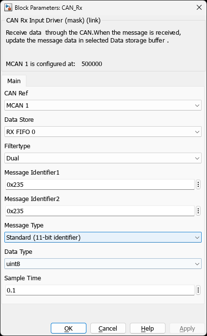
Screenshots taken with chip SAME70Q21B - UFBGA144
Ports
Output Ports
| Port Name | Data Type | Size | Description |
|---|---|---|---|
| MsgID | uint16 or uint32 | Scalar (1) | Received message identifier (uint16 for standard, uint32 for extended) |
| MsgLen | uint8 | Scalar (1) | Number of data bytes received (0-8 for CAN 2.0, 0-64 for CAN-FD) |
| Rx[N] | uint8 | Vector (1-64) | Received message data bytes |
Parameters
CAN Module Selection
| Parameter | Description | Valid Values | Default |
|---|---|---|---|
| CAN Module | Selects which CAN peripheral to use (must match CAN Config block) | CAN0, CAN1, MCAN0, MCAN1 (device-dependent) | CAN0 or MCAN0 |
Message Configuration
| Parameter | Description | Valid Values | Default |
|---|---|---|---|
| Message Type | Identifier format to receive | Standard (11-bit ID), Extended (29-bit ID) | Standard |
| Filter Type | How to match incoming messages | Classic (Mask), Dual ID, Range | Classic |
Filter Configuration (Classic Mode)
| Parameter | Description | Valid Values | Default |
|---|---|---|---|
| Message ID | CAN identifier to match (hexadecimal) | 0x000-0x7FF (standard), 0x00000000-0x1FFFFFFF (extended) | 0x100 |
| Message ID Mask | Bitwise mask (1=must match, 0=don’t care) | 0x000-0x7FF (standard), 0x00000000-0x1FFFFFFF (extended) | 0x7FF (exact match) |
Filter Configuration (Dual ID Mode)
| Parameter | Description | Valid Values | Default |
|---|---|---|---|
| Message ID 1 | First CAN identifier to accept | 0x000-0x7FF (standard), 0x00000000-0x1FFFFFFF (extended) | 0x100 |
| Message ID 2 | Second CAN identifier to accept | 0x000-0x7FF (standard), 0x00000000-0x1FFFFFFF (extended) | 0x101 |
Filter Configuration (Range Mode)
| Parameter | Description | Valid Values | Default |
|---|---|---|---|
| Message ID 1 (Min) | Minimum CAN identifier in range | 0x000-0x7FF (standard), 0x00000000-0x1FFFFFFF (extended) | 0x100 |
| Message ID 2 (Max) | Maximum CAN identifier in range | 0x000-0x7FF (standard), 0x00000000-0x1FFFFFFF (extended) | 0x10F |
Buffer Configuration
| Parameter | Description | Options | Default |
|---|---|---|---|
| Data Store | Reception buffer type | RX FIFO 0, RX FIFO 1, Rx Buffer | RX FIFO 0 |
Tip: Use Rx Buffer for single high-priority messages that must never be lost. Use RX FIFO 0/1 for multiple messages of the same type that can be queued.
Data Configuration
| Parameter | Description | Valid Values | Default |
|---|---|---|---|
| Data Type | Data output port type | uint8, uint16, uint32 | uint8 |
| Data Size | Size of data output port | 1-8 (CAN 2.0), 1-64 (CAN-FD) | 8 |
Message Filtering
Filter Types Explained
1. Classic Filter (Mask-Based)
Compares incoming message ID with configured ID using bitwise AND with mask:
Filter Logic:
  Accept if: (Incoming_ID & Mask) == (Filter_ID & Mask)

Example 1 - Exact Match:
  Filter ID:  0x123
  Mask:       0x7FF (all bits must match)
  Accepts:    0x123 only
  Rejects:    0x122, 0x124, all others

Example 2 - Partial Match:
  Filter ID:  0x100
  Mask:       0x7F0 (ignore lower 4 bits)
  Accepts:    0x100, 0x101, 0x102...0x10F (16 IDs)
  Rejects:    0x110, 0x0FF, all others

Example 3 - Don't Care Bits:
  Filter ID:  0x200
  Mask:       0x700 (only check upper 3 bits)
  Accepts:    0x200-0x2FF (256 IDs)
  Rejects:    0x100, 0x300, all others
2. Dual ID Filter
Accepts messages matching either of two specific IDs:
Filter Logic:
  Accept if: (Incoming_ID == ID1) OR (Incoming_ID == ID2)

Example:
  ID1:        0x200
  ID2:        0x300
  Accepts:    0x200, 0x300 only
  Rejects:    All other IDs

Use Case:
  - Two related messages to same processing
  - Status from two different sources
  - Command and acknowledgment pairing
3. Range Filter
Accepts any message ID within a specified range (inclusive):
Filter Logic:
  Accept if: (ID1 <= Incoming_ID <= ID2)

Example:
  ID1 (Min):  0x100
  ID2 (Max):  0x10F
  Accepts:    0x100, 0x101, 0x102...0x10F (16 IDs)
  Rejects:    0x0FF, 0x110, all others

Use Case:
  - Group of related sensors (0x200-0x20F)
  - Module address range (0x300-0x3FF)
  - Priority band filtering
Filter Priority and Matching Order
When multiple filters are configured, the CAN controller processes them in order:
Incoming Message (ID: 0x105)
        │
        ▼
   ┌─────────────────┐
   │ Standard Filters │ (processed first)
   │  Filter 1: 0x100-0x10F (Range) → MATCH! → RX FIFO 0
   │  Filter 2: 0x105 (Exact)       → (not checked, already matched)
   └─────────────────┘
        │
        ▼
   ┌─────────────────┐
   │ Extended Filters │ (only if no standard match)
   │  Filter 3: ...
   └─────────────────┘

Result: Message accepted by Filter 1, stored in RX FIFO 0
Buffer Modes Comparison
| Feature | RX FIFO 0/1 | Rx Buffer |
|---|---|---|
| Storage Type | First-In-First-Out queue | Dedicated single message buffer |
| Capacity | Multiple messages (configured depth) | One message per buffer |
| Overflow Behavior | Newest message overwrites oldest (watermark) | New message rejected if not read |
| Use Case | Multiple messages of same type, bursty traffic | Single critical message, guaranteed delivery |
| Filter Sharing | Multiple filters can target same FIFO | One filter per buffer |
| Read Access | Sequential (FIFO order) | Direct (always latest) |
Filter Configuration Examples
Common Filter Patterns
/* Example 1: Accept single ID (0x123) */
Message ID:   0x123
Mask:         0x7FF  (all bits must match)
Result:       Accepts 0x123 only

/* Example 2: Accept range (0x100-0x10F) */
Filter Type:  Range
ID1 (Min):    0x100
ID2 (Max):    0x10F
Result:       Accepts 16 IDs from 0x100 to 0x10F

/* Example 3: Accept two specific IDs */
Filter Type:  Dual
ID1:          0x200
ID2:          0x300
Result:       Accepts 0x200 or 0x300 only

/* Example 4: Accept group (0x200-0x2FF, ignore lower byte) */
Message ID:   0x200
Mask:         0x700  (check upper 3 bits only)
Result:       Accepts 0x200-0x2FF (256 IDs)

/* Example 5: Accept all (broadcast receiver) */
Message ID:   0x000
Mask:         0x000  (no bits need to match)
Result:       Accepts all IDs (0x000-0x7FF)
Examples
Example 1: Single ID Reception
Application: Receive motor speed command (ID 0x100)
Simulink Model:
                      CAN Rx
                    (ID: 0x100)
                    ┌──────────┐
  CAN Bus ─────────→│  MsgID   │────→ [Check ID = 0x100]
                    │  MsgLen  │────→ [Validate length]
                    │  Rx[8]   │────→ [speed_cmd, mode, ...]
                    └──────────┘

Configuration:
  - CAN Module: CAN0
  - Message Type: Standard (11-bit)
  - Filter Type: Classic
  - Message ID: 0x100
  - Mask: 0x7FF (exact match)
  - Data Store: Rx Buffer
  - Data Size: 8 bytes

Filter Behavior:
  Accepts: ID 0x100 only
  Rejects: All other IDs
Example 2: ID Range Reception
Application: Receive sensor data from multiple nodes (ID 0x200-0x20F)
Simulink Model:
                      CAN Rx
                   (ID: 0x200-0x20F)
                    ┌──────────┐
  CAN Bus ─────────→│  MsgID   │────→ [Node ID = MsgID - 0x200]
                    │  MsgLen  │────→ [Validate]
                    │  Rx[4]   │────→ [temp, hum, pres, rsv]
                    └──────────┘
                           │
                           ▼
                    ┌─────────────┐
                    │ Demux by ID │
                    │  (Switch)   │
                    └─────────────┘
                      │  │  │  │
                      ▼  ▼  ▼  ▼
                    Node0...Node15

Configuration:
  - Message Type: Standard
  - Filter Type: Range
  - ID1 (Min): 0x200
  - ID2 (Max): 0x20F
  - Data Store: RX FIFO 0
  - Data Size: 4 bytes

Filter Behavior:
  Accepts: 0x200, 0x201, 0x202...0x20F (16 IDs)
  Rejects: 0x1FF, 0x210, all others
Example 3: Broadcast Reception
Application: Receive network-wide broadcast messages
Network Topology:
  ┌──────┐   ┌──────┐   ┌──────┐   ┌──────┐
  │Node 1│   │Node 2│   │Node 3│   │Node 4│
  └───┬──┘   └───┬──┘   └───┬──┘   └───┬──┘
      └──────────┴──────────┴──────────┘
                CAN Bus (250 kbps)

Master broadcasts: ID 0x000 (time sync, emergency stop)
All nodes receive using CAN Rx:

Configuration:
  - Message Type: Standard
  - Filter Type: Classic
  - Message ID: 0x000
  - Mask: 0x7FF (exact match)
  - Data Store: RX FIFO 0 (all nodes)

Broadcast Use Cases:
  - Network time synchronization
  - Emergency stop commands
  - Configuration updates
  - State machine transitions
Example 4: Multi-Filter Node
Application: Motor controller receiving commands and status
Motor Control Node:
  ┌────────────────────────────────────┐
  │                                    │
  │  CAN Rx (0x100)                    │
  │  → Motor Command                   │
  │  [speed_setpoint][mode][enable]    │
  │                                    │
  │  CAN Rx (0x200-0x20F)              │
  │  → Sensor Feedback Range           │
  │  [sensor_id][value][status]        │
  │                                    │
  │  CAN Rx (0x000)                    │
  │  → Emergency Broadcast             │
  │  [emergency_stop][reason]          │
  │                                    │
  └────────────────────────────────────┘
           ▲
           │
       CAN Bus

Filter Configuration (3 CAN Rx blocks):
  1. Command:    ID=0x100, Mask=0x7FF → Rx Buffer
  2. Sensors:    ID1=0x200, ID2=0x20F (Range) → RX FIFO 0
  3. Emergency:  ID=0x000, Mask=0x7FF → Rx Buffer

Priority:
  - 0x000: Highest (emergency - dedicated buffer)
  - 0x100: High (command - dedicated buffer)
  - 0x200-0x20F: Medium (sensors - FIFO queue)
Example 5: CAN-FD Reception (SAM E7x)
Application: Receive firmware update packets with 64-byte payload
Firmware Update Protocol:
                      CAN Rx (CAN-FD)
                      (ID: 0x500)
                    ┌──────────────┐
  CAN-FD Bus ──────→│  MsgID       │────→ 0x500 (update packet)
  (2 Mbps data)     │  MsgLen      │────→ 64 (bytes)
                    │  Rx[64]      │────→ [packet_data]
                    └──────────────┘
                           │
                           ▼
                    ┌──────────────┐
                    │ Packet Parser│
                    │ [seq][data]  │
                    └──────────────┘

Configuration:
  - CAN Module: MCAN0
  - Enable CAN-FD: On
  - Message Type: Standard
  - Filter Type: Classic
  - Message ID: 0x500
  - Mask: 0x7FF
  - Data Store: RX FIFO 0
  - Data Size: 64 bytes

Performance:
  - 64 bytes per packet
  - ~1000 packets/sec @ 2 Mbps data phase
  - ~64 kB/sec throughput
  - Firmware update time: ~16 sec for 1 MB
Troubleshooting
Common Reception Issues
            Missing CAN Config block in model
            CAN module mismatch between Config and Rx blocks
            Incorrect filter configuration (ID/mask mismatch)
            No messages with matching ID on bus
            Bus-off error state or physical connection issue

        Solutions:

            Verify CAN Config block exists and matches Rx block CAN module
            Use CAN bus analyzer to confirm expected messages are present
            Test with broadest filter first (mask=0x000, accept all)
            Check filter type matches incoming message type (standard vs extended)
            Verify bus termination and hardware connections


            Cache coherency issues (ARM Cortex-M7 with DCache)
            Data type mismatch between Tx and Rx
            Buffer overrun (FIFO overflow)
            Endianness mismatch (multi-byte values)

        Solutions:

            Place CAN buffers in non-cached memory (TCM) on SAM E7x
            Use cache invalidate before reading (SCB_InvalidateDCache_by_Addr)
            Ensure consistent data types across network nodes
            Increase FIFO depth or use dedicated Rx buffer
            Verify byte order for 16/32-bit values


            Verify message type matches (standard vs extended ID)
            Check mask calculation: 1=must match, 0=don't care
            Test with exact match first (mask=0x7FF or 0x1FFFFFFF)
            Verify ID1 ≤ ID2 for range filters
            Check for filter ordering conflicts (first match wins)
FIFO Overflow Handling
| Issue | Symptom | Solution |
|---|---|---|
| Messages lost | Missing sequence numbers, gaps in data | Increase FIFO depth, reduce message rate, process faster |
| FIFO full error | Overflow interrupt, watermark exceeded | Monitor fill level, implement flow control |
| Old data received | Stale messages processed | Flush FIFO on overflow, timestamp validation |
| Unpredictable behavior | Intermittent message loss | Use dedicated buffer for critical messages |
Debug Checklist
- ✓ Verify CAN Config block present and configured correctly
- ✓ Check CAN module selection matches between Config and Rx blocks
- ✓ Confirm message type (standard/extended) matches filter configuration
- ✓ Test filter with broadest setting first (accept all IDs)
- ✓ Use CAN bus analyzer to verify transmitted messages
- ✓ Check filter mask calculation (1=match, 0=ignore)
- ✓ Verify data size matches expected message length
- ✓ Monitor FIFO fill level for overflow conditions
- ✓ Test with simple constant ID before complex filtering
- ✓ Check cache coherency on ARM Cortex-M7 devices
Implementation Details
Reception Process (SAM E7x MCAN)
/* CAN Rx Implementation */

    /* Extract message header */
    msg->id = rxBuf->ID;
    msg->extended = rxBuf->XTD;
    msg->rtr = rxBuf->RTR;
    msg->dlc = rxBuf->DLC;

    /* Determine actual data length from DLC */

    /* Copy data from buffer */

    /* Get filter index that matched */
    msg->filter_idx = rxBuf->FIDX;

    /* Acknowledge reception */

### Filter Configuration (SAM E5x/C2x)
/* Standard ID Filter Setup */ void CAN_ConfigStandardFilter(uint8_t filterIdx, uint16_t id1, uint16_t id2, FilterType_t type,
/* Configure filter based on type */

    case FILTER_DUAL:
        filter->MCAN_SIDFE_0 =
            MCAN_SIDFE_0_SFT(1) |        // Dual ID filter
            MCAN_SIDFE_0_SFID1(id1) |    // First ID
            MCAN_SIDFE_0_SFID2(id2) |    // Second ID
            MCAN_SIDFE_0_SFEC(action);
        break;

    case FILTER_CLASSIC:
        filter->MCAN_SIDFE_0 =
            MCAN_SIDFE_0_SFT(2) |        // Classic filter
            MCAN_SIDFE_0_SFID1(id1) |    // Filter ID
            MCAN_SIDFE_0_SFID2(id2) |    // Mask
            MCAN_SIDFE_0_SFEC(action);
        break;
}

/* Flush cache to ensure filter is written */
SCB_CleanDCache_by_Addr((uint32_t*)filter, sizeof(*filter));
}
## References

- ISO 11898-1:2015 - CAN Protocol Specification
- Bosch CAN FD Specification Version 1.0
- [SAM E70/S70/V70/V71 Family Datasheet (DS60001527)](https://www.microchip.com/DS60001527) - MCAN Module
- [SAM E5x/D5x Family Datasheet (DS60001507)](https://www.microchip.com/DS60001507) - CAN Module
- Application Note: CAN Message Filtering and Buffer Management (search [Microchip Portal](https://www.microchip.com))
- Application Note: CAN-FD Implementation and Migration (search [Microchip Portal](https://www.microchip.com))

- [SAM E70/S70/V70/V71 Family Datasheet (DS60001527)](https://www.microchip.com/DS60001527)
- [SAM E5x/D5x Family Datasheet (DS60001507)](https://www.microchip.com/DS60001507)

- [Microchip Portal](https://www.microchip.com/en-us/search)
- [Microchip Portal](https://www.microchip.com/en-us/search)
## Related Blocks

- [CAN Config](../../../block/communication/can/can_config) - Configure CAN peripheral and buffers
- CAN Tx - Transmit CAN messages
- Digital Output - Control CAN transceiver enable pins
- Interrupt Config - Configure CAN reception interrupts