CAN Tx


The CAN Tx block transmits CAN messages on the CAN bus network. It accepts message data and length as inputs, and sends the message with the configured ID and format. The block supports both standard (11-bit) and extended (29-bit) identifiers, remote transmission requests (RTR), and both dedicated buffer and FIFO transmission modes.
This block requires a CAN Config block in the same model to configure the CAN peripheral. Multiple CAN Tx blocks can be used to send different messages on the same CAN module.
When to use:
- Send CAN messages — Transmit commands, status, or telemetry over CAN bus
- Multi-message transmission — Send different message IDs (multiple Tx blocks)
- Priority messages — Use dedicated buffers for time-critical high-priority messages
- CAN-FD bulk data — Send up to 64 bytes per message (SAM devices)
- RTR frames — Request data from other CAN nodes
When NOT to use:
- No CAN Config — Always add CAN Config block first (Tx block requires it)
- Receive messages — Use CAN Rx block instead
- UART/SPI/I2C — Use protocol-specific Tx blocks (not CAN-based)
- dsPIC/PIC32 targets — CAN Tx currently supports SAM devices only
- Point-to-point links — UART simpler for single transmitter/receiver
Block Dialog
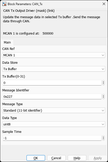
Screenshots taken with chip SAME70Q21B - UFBGA144
Ports
Input Ports
| Port Name | Data Type | Size | Description |
|---|---|---|---|
| MsgLen | uint8 | Scalar (1) | Number of data bytes to transmit (0-8 for CAN 2.0, 0-64 for CAN-FD) |
| Tx[N] | uint8 | Vector (1-64) | Message data bytes to transmit |
Parameters
CAN Module Selection
| Parameter | Description | Valid Values | Default |
|---|---|---|---|
| CAN Module | Selects which CAN peripheral to use (must match CAN Config block) | CAN0, CAN1, MCAN0, MCAN1 (device-dependent) | CAN0 or MCAN0 |
Message Configuration
| Parameter | Description | Valid Values | Default |
|---|---|---|---|
| Message Type | Identifier format | Standard (11-bit ID), Extended (29-bit ID) | Standard |
| Message ID | CAN identifier (hexadecimal) | 0x000-0x7FF (standard), 0x00000000-0x1FFFFFFF (extended) | 0x100 |
| Remote Transmission Request (RTR) | Send RTR frame instead of data frame | Enable / Disable | Disable |
Buffer Configuration
| Parameter | Description | Options | Default |
|---|---|---|---|
| Data Store | Transmission buffer type | Tx FIFO, Tx Buffer | Tx FIFO |
Tip: Use Tx Buffer for time-critical, high-priority messages that must be sent immediately. Use Tx FIFO for lower priority messages that can be queued.
Data Configuration
| Parameter | Description | Valid Values | Default |
|---|---|---|---|
| Data Type | Data input port type | uint8, uint16, uint32 | uint8 |
| Data Size | Size of data input port | 1-8 (CAN 2.0), 1-64 (CAN-FD) | 8 |
CAN Message Structure
Standard CAN 2.0 Frame
|SOF| ID (11-bit) |RTR|IDE|r0| DLC |   DATA (0-8 bytes)   | CRC |ACK|EOF|
 1b     11 bits    1b  1b 1b  4b         0-64 bits         15b  2b  7b

SOF: Start of Frame
ID:  Message Identifier (11-bit standard or 29-bit extended)
RTR: Remote Transmission Request
IDE: Identifier Extension (0=standard, 1=extended)
DLC: Data Length Code (0-8 bytes for CAN 2.0)
CRC: Cyclic Redundancy Check
ACK: Acknowledge
EOF: End of Frame
Extended CAN 2.0 Frame
|SOF| ID Base |SRR|IDE| ID Extended (18-bit) |RTR|r1|r0| DLC | DATA | CRC |ACK|EOF|
 1b   11-bit   1b  1b       18 bits            1b  1b 1b  4b  0-8B  15b  2b  7b

ID = ID_Base (11-bit) + ID_Extended (18-bit) = 29-bit total
CAN-FD Frame (SAM E5x/E7x only)
|SOF| ID |IDE|FDF|res|BRS|ESI| DLC |   DATA (0-64 bytes)   | CRC |ACK|EOF|
                          Fast Data Phase (up to 8 Mbps)

FDF: FD Format indicator
BRS: Bit Rate Switch (data phase can be faster)
ESI: Error State Indicator
DLC: 0-15 (maps to 0,1,2...8,12,16,20,24,32,48,64 bytes)
Message Priority and Arbitration
CAN Bus Arbitration
CAN uses CSMA/CA (Carrier Sense Multiple Access with Collision Avoidance). Lower message IDs have higher priority:
Priority Order (highest to lowest):
  ID 0x000 → Highest priority (wins arbitration)
  ID 0x001
  ID 0x002
  ...
  ID 0x7FF → Lowest priority (standard ID)

Example arbitration:
  Node A transmits ID 0x100 (0001 0000 0000)
  Node B transmits ID 0x101 (0001 0000 0001)
  → Node A wins (bit 0 is dominant), Node B stops and retries
Best Practice: Assign lower IDs to time-critical messages:
- 0x000-0x0FF: High-priority control commands, emergency stop
- 0x100-0x1FF: Motor control, sensor feedback
- 0x200-0x3FF: Status updates, diagnostic messages
- 0x400-0x7FF: Low-priority telemetry, logging
Remote Transmission Request (RTR)
RTR Frame Usage
RTR frames request data from another node without sending payload data:
/* RTR Frame Structure */
RTR Frame:
  - Same ID as data frame being requested
  - RTR bit set to 1
  - DLC indicates expected data length
  - No data bytes transmitted

Example Use Case:
  Master requests sensor data from slave:
    1. Master sends RTR: ID=0x300, DLC=4, RTR=1
    2. Slave responds: ID=0x300, DLC=4, Data=[temp,hum,pres,rsv]
Transmission Modes Comparison
| Feature | Tx FIFO | Tx Buffer |
|---|---|---|
| Transmission Order | First-In-First-Out queue | Immediate (based on priority) |
| Priority Handling | Messages queued, sent in order | Hardware priority based on ID |
| Latency | Variable (depends on queue depth) | Minimal (direct access) |
| Use Case | General-purpose messaging | Time-critical, high-priority messages |
| Overflow Behavior | Oldest message may be lost | New message rejected if buffer full |
| Configuration Complexity | Simple (shared FIFO) | Requires dedicated buffer allocation |
Examples
Example 1: Periodic Sensor Data Transmission
Application: Send temperature sensor data every 100ms
Simulink Model:
  ┌─────────────┐     ┌──────────┐
  │  Constant   │────→│  MsgLen  │
  │   (uint8)   │     │          │    CAN Tx
  │      4      │     │    Tx    │   (ID: 0x210)
  └─────────────┘     │          │
                      │  [temp]  │
  ┌─────────────┐     │  [hum]   │
  │  Sensors    │────→│  [pres]  │───→ CAN Bus
  │  [4 bytes]  │     │  [rsv]   │
  └─────────────┘     └──────────┘

Configuration:
  - CAN Module: CAN0
  - Message Type: Standard (11-bit)
  - Message ID: 0x210
  - Data Store: Tx FIFO
  - Data Size: 4 bytes
  - Sample Time: 0.1 (100ms)
Example 2: Event-Triggered Command Transmission
Application: Send motor control command on button press
Simulink Model:
  ┌─────────────┐     ┌──────────┐
  │  Button     │     │ Enabled  │
  │  Pressed    │────→│ Subsystem│
  └─────────────┘     │          │
                      │ ┌──────┐ │
  ┌─────────────┐     │ │MsgLen│ │    CAN Tx
  │  Constant   │────→│ │      │ │   (ID: 0x100)
  │      2      │     │ │  Tx  │ │
  └─────────────┘     │ │[cmd] │ │
                      │ │[val] │ │───→ CAN Bus
  ┌─────────────┐     │ └──────┘ │
  │ Command     │────→│          │
  │ [speed_cmd] │     │          │
  └─────────────┘     └──────────┘

Configuration:
  - Message Type: Extended (29-bit)
  - Message ID: 0x18FF0100
  - Data Store: Tx Buffer (high priority)
  - Data Size: 2 bytes
  - Triggering: Event-based (not periodic)
Example 3: Multi-Message Node
Application: Motor controller sending multiple message types
CAN Network Node:
  ┌───────────────────────────────────┐
  │        Motor Control Node         │
  │                                   │
  │  ┌─────────┐  CAN Tx (0x100)     │
  │  │ Speed   │  → Motor Command     │───┐
  │  │ Control │  [setpoint][mode]    │   │
  │  └─────────┘                      │   │
  │                                   │   │
  │  ┌─────────┐  CAN Tx (0x200)     │   │
  │  │ Current │  → Status Feedback   │   ├──→ CAN Bus
  │  │ Sensor  │  [curr][volt][temp]  │   │    (250 kbps)
  │  └─────────┘                      │   │
  │                                   │   │
  │  ┌─────────┐  CAN Tx (0x300)     │   │
  │  │ Fault   │  → Error Report      │───┘
  │  │ Monitor │  [error_code][data]  │
  │  └─────────┘                      │
  └───────────────────────────────────┘

Message Priority:
  0x100: Motor command (highest priority - wins arbitration)
  0x200: Status feedback (medium priority)
  0x300: Error report (lower priority, but critical)

Transmission Rates:
  0x100: 10 Hz (100ms)
  0x200: 50 Hz (20ms)
  0x300: Event-triggered (faults only)
Example 4: CAN-FD High-Throughput Data
Application: Vision system transmitting image data (SAM E70 only)
CAN-FD Configuration:
  ┌─────────────┐     ┌──────────┐
  │  Constant   │────→│  MsgLen  │
  │   (uint8)   │     │          │    CAN Tx
  │     64      │     │          │   (ID: 0x400)
  └─────────────┘     │    Tx    │    CAN-FD
                      │ [64 bytes]│
  ┌─────────────┐     │          │
  │ Image Chunk │────→│  Image   │───→ CAN-FD Bus
  │  64 bytes   │     │   Data   │    (500k nominal
  └─────────────┘     └──────────┘     2M data phase)

Configuration:
  - CAN Module: MCAN0
  - Enable CAN-FD: On
  - Message Type: Standard
  - Message ID: 0x400
  - Data Store: Tx FIFO
  - Data Size: 64 bytes
  - Nominal Rate: 500 kbps (arbitration)
  - Data Rate: 2 Mbps (payload)

Performance:
  - 64 bytes per message
  - ~1000 messages/sec
  - ~64 kB/sec throughput (vs 8 kB/sec for CAN 2.0)
Troubleshooting
Common Transmission Issues
            Missing CAN Config block in model
            CAN module mismatch between Config and Tx blocks
            Bus-off error state (CAN peripheral disabled)
            Tx buffer full (dedicated buffer mode)
            Arbitration continuously lost (message ID too low priority)

        Solutions:

            Verify CAN Config block exists and matches Tx block CAN module
            Check CAN error status registers for bus-off condition
            Use Tx FIFO instead of dedicated buffer for non-critical messages
            Review message ID priority (lower ID = higher priority)
            Monitor bus load and reduce transmission frequency if needed


            Assign lower IDs to time-critical messages
            Use dedicated Tx buffers for high-priority messages
            Reduce overall bus utilization (lower transmission rates)
            Implement bus load monitoring and adaptive transmission


            Incorrect MsgLen value (length mismatch)
            Data type mismatch between Tx and Rx blocks
            Cache coherency issues (ARM Cortex-M7 with DCache)
            Buffer overwritten before transmission completes

        Solutions:

            Verify MsgLen input matches actual data size
            Ensure consistent data types across Tx/Rx blocks
            Place CAN buffers in non-cached memory (TCM) on SAM E7x
            Use cache maintenance functions (SCB_CleanDCache_by_Addr)
Performance Optimization
| Issue | Symptom | Optimization |
|---|---|---|
| High transmission latency | Messages delayed beyond acceptable limits | Use dedicated Tx buffer instead of FIFO, reduce bus load |
| Buffer overflow | Messages dropped, transmission errors | Increase Tx FIFO size, reduce transmission rate |
| Poor bus utilization | Bus idle while messages pending | Optimize message packing, use CAN-FD for bulk data |
| Excessive CPU load | Interrupt overhead from frequent transmissions | Batch messages, use DMA-based transmission (SAM E7x) |
Debug Checklist
- ✓ Verify CAN Config block present and configured correctly
- ✓ Check CAN module selection matches between Config and Tx blocks
- ✓ Confirm message ID is valid for selected type (standard/extended)
- ✓ Verify MsgLen input value matches data port size
- ✓ Check bus termination and hardware connections
- ✓ Monitor CAN error counters (TEC/REC) for bus health
- ✓ Use CAN bus analyzer to verify actual transmitted messages
- ✓ Check for arbitration loss patterns (message priority issues)
- ✓ Verify data type consistency between Tx and Rx blocks
- ✓ Test with simple constant data before using complex signals
Implementation Details
Transmission Process (SAM E7x MCAN)
/* CAN Tx Implementation */

    /* Select buffer (FIFO or dedicated) */

    /* Configure message header */
    txBuf->ID = id;
    txBuf->XTD = extended ? 1 : 0;  // Extended ID flag
    txBuf->RTR = 0;                 // Data frame (not RTR)
    txBuf->DLC = len;               // Data length code
    txBuf->FDF = 0;                 // CAN 2.0 (not CAN-FD)
    txBuf->BRS = 0;                 // No bit rate switching

    /* Copy data to buffer */

    /* Flush cache if using cached memory */
    SCB_CleanDCache_by_Addr((uint32_t*)txBuf, sizeof(*txBuf));

    /* Trigger transmission */

### CAN-FD Transmission (SAM E5x/E7x)
/* CAN-FD Transmission with up to 64 bytes */
/* DLC encoding for CAN-FD */
uint8_t dlc;

/* Configure CAN-FD message */
txBuf->ID = id;
txBuf->XTD = 0;     // Standard ID
txBuf->RTR = 0;     // Data frame
txBuf->DLC = dlc;   // DLC encoded
txBuf->FDF = 1;     // CAN-FD format
txBuf->BRS = 1;     // Bit rate switching enabled

/* Copy data */
memcpy(txBuf->buffer.c, data, len);

/* Cache maintenance and trigger */
SCB_CleanDCache_by_Addr((uint32_t*)txBuf, sizeof(*txBuf));
MCAN0_REGS->MCAN_TXBAR = 0x01;
}
## References

- ISO 11898-1:2015 - CAN Protocol Specification
- Bosch CAN FD Specification Version 1.0
- [SAM E70/S70/V70/V71 Family Datasheet (DS60001527)](https://www.microchip.com/DS60001527) - MCAN Module
- [SAM E5x/D5x Family Datasheet (DS60001507)](https://www.microchip.com/DS60001507) - CAN Module
- Application Note: CAN Message Prioritization and Bus Load Optimization (search [Microchip Portal](https://www.microchip.com))

- [SAM E70/S70/V70/V71 Family Datasheet (DS60001527)](https://www.microchip.com/DS60001527)
- [SAM E5x/D5x Family Datasheet (DS60001507)](https://www.microchip.com/DS60001507)

- [Microchip Portal](https://www.microchip.com/en-us/search)
## Related Blocks

- [CAN Config](../../../block/communication/can/can_config) - Configure CAN peripheral and buffers
- CAN Rx - Receive CAN messages with filtering
- Digital Input - Monitor CAN transceiver status pins
- Timer Output - Generate periodic transmission triggers