Digital Input


Overview
The Digital Input block reads the state of digital input pins from any available GPIO port on Microchip microcontrollers. Selected pins are configured as digital inputs with user-selectable pull-up, pull-down, or hi-impedance modes. When the block output is defined as one uint16, users should only use bits corresponding to the selected pins.
When to use:
- Reading button/switch states
- Monitoring external digital signals
- Interfacing with digital sensors
- Reading encoder signals
When NOT to use:
- For pins that require analog input (use ADC block instead)
- For pins configured as outputs elsewhere in the model
Block Dialog
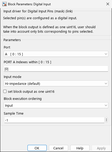
Screenshots taken with chip 33AK512MPS512
Ports
Output
| Port | Data Type | Description |
|---|---|---|
| Port signal | boolean or uint16 | Digital state of selected pin(s). If multiple pins are selected without PACK option, each pin has its own boolean output. If PACK option is enabled, a single uint16 output contains pin states in corresponding bit positions. |
Parameters
| Parameter | Variable | Type | Description |
|---|---|---|---|
| Port | PORT | popup | GPIO port selection (A, B, C, etc.). Dynamically populated based on target device pin map. Shows available pin indices for each port. |
| Pins | PIN | edit | Array of pin indices to read, e.g., [0] or [0 1 2]. Valid range is [0..15] for 16-bit ports or [0..31] for 32-bit ports. Out-of-range or unavailable pins are automatically filtered out with a warning. |
| Input mode | INPUT_PIN_MODE | popup | Chip-dependent. Electrical configuration: Hi-impedance (default), Pull-up, or Pull-down. Only visible on newer dsPIC and PIC32 chips (Arch 1,2,3,4,8 with CN.type==2). Hidden on older dsPIC and all SAM devices. |
| set block output as one uint16/uint32 | PACK | checkbox | Conditional. When enabled, all selected pins are packed into a single uint16 (16-bit ports) or uint32 (32-bit ports) output with bits corresponding to pin numbers. When disabled, each pin has an individual boolean output. Always visible. |
| Request exact simultaneous sampling | SIMULTANEOUS | checkbox | Conditional. When enabled, all pins are read in a single PORT register access for atomic simultaneous sampling. Only visible when multiple pins are selected AND PACK is disabled. |
| Block execution ordering | ORDERING | popup | Controls block scheduling: None, Input, Output, or Input & Output. |
| Sample Time | SampleTime | edit | Sampling interval in seconds. Use -1 for inherited sample time. |
Device Support
Input Mode Parameter Visibility:
- Visible: dsPIC30F, dsPIC33F, dsPIC33E, dsPIC33C, dsPIC33A, PIC32, PIC32A (Arch 1,2,3,4,8 with CN.type==2)
- Hidden: Older dsPIC chips with CN.type≠2, all SAM (SAME70/SAMS70/SAMV71/SAMx2/SAMx5) devices
- When hidden, pins default to Hi-impedance mode
Output Data Type:
- 16-bit ports (dsPIC): PACK mode outputs
uint16, unpacked mode outputs individualbooleanper pin - 32-bit ports (SAM/PIC32A): PACK mode outputs
uint32, unpacked mode outputs individualbooleanper pin
Port Availability:
- The Port popup is dynamically populated from the chip pin map at model initialization
- Only ports with at least one available digital pin are shown
- Pin indices shown in brackets reflect actual chip capabilities (e.g.,
A [0:15]orB [0 2 4 8])
Examples
Programmatic Setup
% Add block to model
add_block('MCHP_Blockset/Digital IO/Digital Input', [mdl '/DigitalIn']);

% Configure key parameters
set_param([mdl '/DigitalIn'], 'PORT', 'A');
set_param([mdl '/DigitalIn'], 'PIN', '[0 1 2]');
set_param([mdl '/DigitalIn'], 'INPUT_PIN_MODE', 'Pull-up');
Troubleshooting
Problem: Block output always reads 0 or 1 regardless of input
- Solution: Check that the pin is not configured as an output elsewhere in the model. Verify ANSEL configuration if the pin has analog capability.
Problem: Floating input causes unstable readings
- Solution: Enable pull-up or pull-down resistor in the Input mode parameter, or add external resistors to your circuit.
Problem: Multiple pins don’t update simultaneously
- Solution: All pins on the same port are read atomically from the PORT register in a single instruction. If pins are on different ports, they will be read sequentially.
Related Blocks
- Digital Output — Write to digital output pins
- Digital Output Write — Direct output write block
- Digital Output Read — Read output latch state