PDEC - Position Decoder for SAM Devices


Overview
The MCHP_PDEC block provides an interface to the Position Decoder (PDEC) peripheral on SAM E5x and E7x microcontrollers. Unlike traditional quadrature encoders, PDEC is optimized for Hall effect sensors (3-phase BLDC motors) and stepper motor position tracking, with specialized features for these applications.
When to use:
- Hall sensors — Decode 3-phase Hall sensor signals for BLDC motor position (6-step)
- SAM E5x/E7x only — Dedicated PDEC peripheral on these ARM Cortex-M devices
- 9-bit angular resolution — Fine position within each Hall sector for smooth FOC
- Stepper motors — Track step/direction inputs for open-loop stepper position
- Auto-correction — Built-in phase error correction for Hall sensor glitches
When NOT to use:
- Quadrature encoders — Use QDEC SAMx or QEI blocks (optimized for A/B/Index signals)
- dsPIC/PIC32 targets — PDEC only on SAM E5x/E7x (use QEI for dsPIC)
- Other SAM families — PDEC not available on SAM C2x/D2x (use QDEC SAMx)
- No Hall sensors — If using incremental encoder, use QDEC SAMx block instead
- Software decoding sufficient — If Hall speed low, GPIO + software may be simpler Key Features:
- 3-input position decoder (Hall sensors: A, B, C)
- Quadrature encoder mode (X2/X4)
- Counter with direction input mode
- Configurable position counter and revolution counter
- Auto-correction for phase errors
- Programmable digital filtering
- Index pulse support
- Angular position calculation (9-bit + configurable resolution)
Device Support
| Family | PDEC Module | Features |
|---|---|---|
| SAM E54/E53/E51 | 1 | Hall sensor, quadrature, stepper position |
| SAM E70/S70/V71 | 1 | Hall sensor, quadrature, stepper position |
Block Dialog
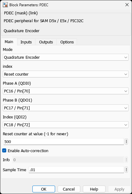
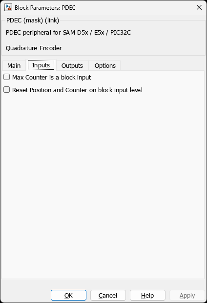
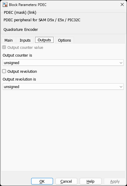
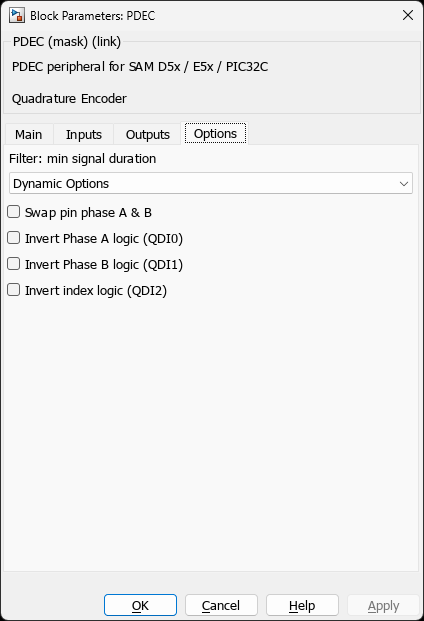
SAME54N20A - TQFP100Parameters
Operating Mode
| Parameter | Options | Description |
|---|---|---|
| Mode | • Quadrature Encoder | • Counter with direction |
Position Configuration
| Parameter | Options | Description |
|---|---|---|
| Counter Output | on/off | Enable position counter output |
| Counter Datatype | unsigned/signed | Position counter sign |
| Revolution Output | on/off | Enable revolution counter |
| Revolution Datatype | unsigned/signed | Revolution counter sign |
| Counter Revolution Length | • Counter is 16-bit (9+7 bit resolution) | • Counter is 17-bit (9+8 bit resolution) |
Index and Reset
| Parameter | Options | Description |
|---|---|---|
| Index | • Not used | • Reset counter |
| Max Counter Reset | Integer value | Modulo limit for position counter |
| Max Position Input | on/off | Enable dynamic modulo limit via block input |
| Reset Input | on/off | Enable external reset input |
Signal Configuration
| Pin | Function (Quadrature) | Function (Hall Sensor) |
|---|---|---|
| QDI0 | Phase A | Hall A |
| QDI1 | Phase B | Hall B |
| QDI2 | Index | Hall C |
| Parameter | Options | Description |
| Invert QDI0/1/2 | on/off | Invert input polarity |
| Swap Pin Phase A & B | on/off | Reverse direction (quadrature mode) |
| Auto Correction | on/off | Automatic phase error correction |
| Digital Filter | disabled or time period | Input signal filtering |
Hall Sensor Operation
3-Phase Hall Sensor Interface
PDEC decodes 3-wire Hall sensor signals for BLDC motor position: Hall Sensor States (6-step commutation): State | Hall A | Hall B | Hall C | Sector ——-|——–|——–|——–|——– 1 | 0 | 0 | 1 | 0-60° 2 | 0 | 1 | 1 | 60-120° 3 | 0 | 1 | 0 | 120-180° 4 | 1 | 1 | 0 | 180-240° 5 | 1 | 0 | 0 | 240-300° 6 | 1 | 0 | 1 | 300-360° Valid transitions: 1→2→3→4→5→6→1 (CW) 1→6→5→4→3→2→1 (CCW)
Angular Position Calculation
// PDEC provides 9-bit angular resolution within each sector Angular_bits = 9; // Fixed 9-bit per sector (0-511) Sector = 0 to 5; // From Hall state// Total position = (Sector * 512) + Angular_position Counts_per_rev = 6 * 512 = 3072; // Convert to electrical angle Electrical_angle_deg = (Position_count / 3072) * 360; // For motor with 4 pole pairs: Mechanical_angle_deg = Electrical_angle_deg / 4;
PDEC Registers (SAM E5x)
// Control Register PDEC->CTRLA.bit.MODE = 0; // QDEC mode PDEC->CTRLA.bit.CONF = 1; // X4 quadrature (secure) PDEC->CTRLA.bit.PINEN = 0b111; // Enable all 3 inputs PDEC->CTRLA.bit.PINVEN = 0b000; // Invert mask PDEC->CTRLA.bit.SWAP = 0; // No pin swap PDEC->CTRLA.bit.PEREN = 1; // Enable period/modulo// Position Counter (16-bit) count = PDEC->COUNT.reg; // Current count (9-bit angular + N-bit revolution)// Angular position (9-bit within sector) angular = count & 0x1FF; // Lower 9 bits// Revolution counter (upper bits) revolution = count » 9; // Upper N bits// Period register (modulo limit) PDEC->CC[0].reg = max_position; // Position wraps at this value// Digital Filter PDEC->FILTER.bit.FILTER = filter_value; // 0=disabled, 1-255=filter clocks
Examples
Example 1: BLDC Motor with Hall Sensors
Application: 3-Phase BLDC Motor Position Feedback
Hardware: BLDC motor with 3 Hall sensors, 4 pole pairs
Configuration:
- Mode: Quadrature Encoder
- Counter Output: on (unsigned)
- Counter Length: 16-bit (9+7, allows 128 revolutions)
- Index: Not used // Position calculation Position_count = PDEC_Output; Angular_9bit = Position_count & 0x1FF; // 0-511 within sector Revolution = Position_count » 9; // Revolution count// Hall sector (0-5) from upper 3 bits of angular position Sector = Angular_9bit » 6; // Approximate sector// Electrical angle (0-360°) Elec_angle_deg = (Position_count % 3072) / 3072 * 360; // Mechanical angle (4 pole pairs) Mech_angle_deg = Elec_angle_deg / 4; // Commutation sector for 6-step drive Commutation_sector = floor(Elec_angle_deg / 60); // 0-5
Example 2: Stepper Motor Position Tracking
Application: Open-Loop Stepper with Position Feedback
Configuration:
- Mode: Counter with direction
- QDI0: Step pulse input
- QDI1: Direction input (HIGH=CW, LOW=CCW)
- Counter Output: 32-bit signed // For 200 steps/rev stepper (1.8° per step) Steps_per_rev = 200; Position_steps = PDEC_Counter; // Convert to angle Angle_deg = (Position_steps % Steps_per_rev) * 1.8; // Full revolutions Revolutions = floor(Position_steps / Steps_per_rev); // Microstep mode: 1/16 microstepping = 3200 steps/rev Microsteps_per_rev = 200 * 16; Microstep_angle_deg = (Position_steps % Microsteps_per_rev) / Microsteps_per_rev * 360;
Example 3: Index-Based Homing
Application: Absolute Position Reference Using Index Pulse
Configuration:
- Mode: Quadrature Encoder
- Index: Reset counter once only
- Auto Correction: on (for Hall sensor noise immunity)
Example 4: Dynamic Modulo Limit
Application: Variable Position Range
Configuration:
- Max Position Input: on
- Counter wraps at value from MAXPOS input port
Troubleshooting
Issue: Incorrect Hall Sequence Detection
Causes:
- Hall sensors wired incorrectly (wrong A/B/C assignment)
- Hall sensor polarity inverted
- One Hall sensor not working (stuck at 0 or 1)
Solutions:
- Use “Invert QDI” options to correct polarity
- Enable Auto Correction for minor glitches
- Verify Hall wiring with multimeter or oscilloscope
- Check Hall sensor power supply (typically 5V or 12V)
Issue: Position Jumps or Glitches
Solution: Enable digital filter to suppress noise. Start with 1 µs filter period and increase if needed.
Issue: Wrong Direction
Solution: Enable “Swap Pin Phase A & B” to reverse counting direction.
References
- SAM E54 Family Datasheet (DS60001507) - PDEC Position Decoder section
- SAM E70 Family Datasheet (DS60001527) - PDEC peripheral
- Atmel Application Note: BLDC Motor Control with Hall Sensors (search Microchip Documentation Portal )
- PDEC Angular Position Calculation: Family reference manual chapter on position decoding (see datasheets above)
Last Updated: 2024 | MCHP Blockset for MATLAB/Simulink
Related Blocks
- MCHP_QEI - Quadrature Encoder Interface for dsPIC/PIC32
- MCHP_QDEC_SAMx - Quadrature Decoder using TC modules
- MCHP_PWM_SAMx - PWM for BLDC motor drive (works with PDEC Hall inputs)