PWM


When to use:
- Motor control and power conversion on dsPIC30F, dsPIC33F, or dsPIC33E (EP/EV/FJ) devices
- Applications requiring up to 4 complementary PWM pairs with dead-time and fault protection
- PWM-synchronized ADC triggering for current/voltage sensing
- Legacy projects targeting older dsPIC families
When NOT to use:
- dsPIC33C/CH/CK devices → use PWM HighSpeed for enhanced features
- dsPIC33A devices → use PWM HS FEP for fine edge placement and high resolution
- SAM devices → use TCC PWM (SAM E5x/C2x) or PWM SAM7x (SAM E7x/S7x/V7x)
Block Dialog
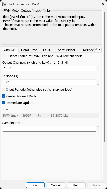
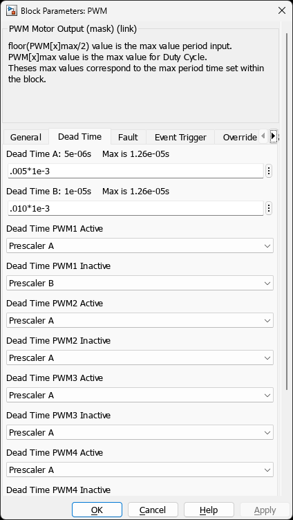
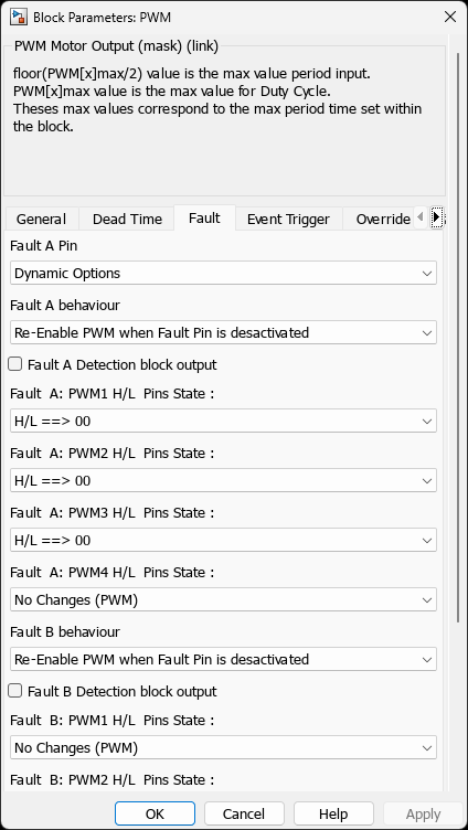
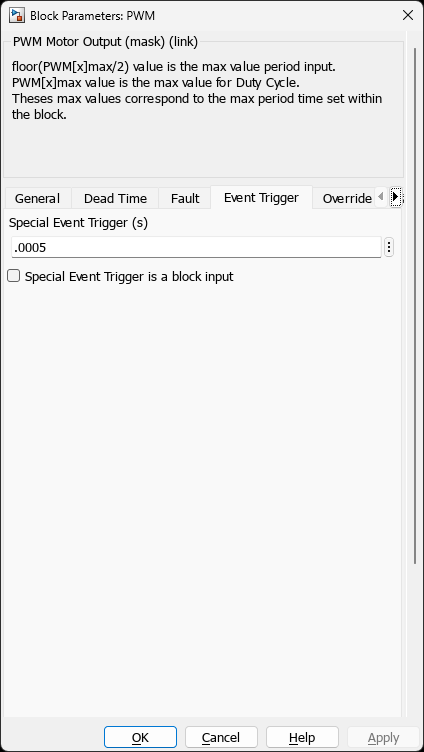
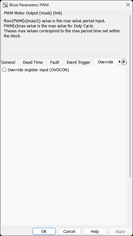
30F4011Ports
Block Inputs
| Input | Type | Condition | Description |
|---|---|---|---|
| Period *1/2 | uint16 | Period input enabled | Global period input. User provides half the actual period value (internally multiplied by 2) |
| DutyCycle 1..4 | uint16 | Channel enabled | Duty cycle values for enabled channels (0 to PWMxmax) |
| EventTrig | uint16 | Special Event Trigger input enabled | Dynamic special event trigger value |
| OVDCON | uint16 | Override input enabled | PWM override control register value |
| Fault A Re-Enable | boolean | Fault A latched mode | Re-enable PWM after latched Fault A |
| Fault B Re-Enable | boolean | Fault B latched mode | Re-enable PWM after latched Fault B (dsPIC33E only) |
Block Outputs
| Output | Type | Description |
|---|---|---|
| Flt A | boolean | Fault A status (1 = fault active) |
| Flt B | boolean | Fault B status (dsPIC33E only) |
Parameters
This block uses a 6-tab GUI dialog. Parameters shown below are visible to users based on chip capabilities.
General Tab
| Parameter | Description |
|---|---|
| PWM | PWM peripheral reference. Options: 1, 2, or Duplicate Ports for PWM x. Only visible if multiple PWM modules available |
| Distinct Enable of PWM High and PWM Low channels | Enable separate control of high-side and low-side channel outputs |
| Output Channels (High and Low) | PWM channels to enable (e.g., [1 2 3 4]). Prompt changes to “Output Channels (Low)” if distinct enable is checked |
| Output Channels (High) | High-side channels to enable. Only visible if distinct enable is checked |
| Periode (s) | PWM period in seconds. Determines PWMxmax workspace variable |
| Input Periode (otherwise set to max periode) | Enable period as block input for variable frequency operation |
| Center Aligned Mode | Enable center-aligned PWM (timer counts up then down). Recommended for motor control |
| Immediate Update | Update duty cycle immediately vs. at period boundary. Off recommended for motor control |
| Info | Read-only field showing calculated PWMxmax value and bit resolution |
| SampleTime | Block sample time. Use -1 for inherited |
Dead Time Tab
| Parameter | Description |
|---|---|
| Dead Time A | Dead-time duration for Prescaler A. Prompt shows effective value and maximum (e.g., “Dead Time A: 5e-06s Max is 1.26e-05s”) |
| Dead Time B | Dead-time duration for Prescaler B. Only visible on dsPIC33E devices |
| Dead Time PWM1 Active | Select Prescaler A or Prescaler B for PWM1 active transition |
| Dead Time PWM1 Inactive | Select Prescaler A or Prescaler B for PWM1 inactive transition |
| Dead Time PWM2 Active | Select prescaler for PWM2 active transition |
| Dead Time PWM2 Inactive | Select prescaler for PWM2 inactive transition |
| Dead Time PWM3 Active | Select prescaler for PWM3 active transition |
| Dead Time PWM3 Inactive | Select prescaler for PWM3 inactive transition |
| Dead Time PWM4 Active | Select prescaler for PWM4 active transition |
| Dead Time PWM4 Inactive | Select prescaler for PWM4 inactive transition |
Note: PWM channel dead-time parameters are only visible if the channel exists on the selected chip and Dead Time B is available.
Fault A Tab
| Parameter | Description |
|---|---|
| Fault A Pin | Fault A input pin selection. Only visible for devices with remappable pins |
| Fault A behaviour | Re-Enable PWM when Fault Pin is desactivated or Use Re-Enable block input after Fault is detected (latched mode) |
| Fault A Detection block output | Enable Flt A output port |
| Fault A: PWM1 H/L Pins State | PWM1 output state during fault: No Changes (PWM), H/L ==> 00, H/L ==> 01, H/L ==> 10, H/L ==> 11 |
| Fault A: PWM2 H/L Pins State | PWM2 output state during fault |
| Fault A: PWM3 H/L Pins State | PWM3 output state during fault |
| Fault A: PWM4 H/L Pins State | PWM4 output state during fault |
Note: PWM channel fault state parameters are only visible if the channel exists on the selected chip.
Fault B Tab
| Parameter | Description |
|---|---|
| Fault B Pin | Fault B input pin selection. Only visible for devices with remappable pins |
| Fault B behaviour | Re-Enable PWM when Fault Pin is desactivated or Use Re-Enable block input after Fault is detected |
| Fault B Detection block output | Enable Flt B output port |
| Fault B: PWM1 H/L Pins State | PWM1 output state during Fault B |
| Fault B: PWM2 H/L Pins State | PWM2 output state during Fault B |
| Fault B: PWM3 H/L Pins State | PWM3 output state during Fault B |
| Fault B: PWM4 H/L Pins State | PWM4 output state during Fault B |
Note: Fault B tab is only available on dsPIC33E devices. Parameters are visible only if Fault B is supported by the selected chip.
Special Event Tab
| Parameter | Description |
|---|---|
| Special Event Trigger (s) | ADC trigger timing in seconds. Set to -1 to disable. Used for PWM-ADC synchronization |
| Special Event Trigger is a block input | Enable EventTrig block input for dynamic trigger adjustment |
Override Tab
| Parameter | Description |
|---|---|
| Override register input (OVDCON) | Enable OVDCON block input for manual PWM output override control |
Scaling
This block uses uint16 raw values for all inputs (period, duty cycle, trigger). User scaling is required.
| Input Type | Range | Scaling | Description |
|---|---|---|---|
| Uint16 raw | 0 to PWMxmax | User handles scaling | Direct register value |
⚠️ Important: The block performs no range checking on inputs. Users must clamp values before the block input (e.g., using a Saturation block) to prevent overflow.
Uint Raw Input
- Uint raw: Integer values transfer directly to peripheral registers with no runtime computation—maximum efficiency.
The block creates a workspace variable for user scaling:
| Variable | Value | Description |
|---|---|---|
PWMxmax | PTPER × 2 - 1 | Maximum duty cycle value (where x = PWM reference number) |
Note: PTPER is computed from the Period parameter. In center-aligned mode, the block internally halves the period before calculating PTPER, resulting in a halved PWMxmax.
Fixed Period (period input disabled):
$$\text{DutyCycle}_\text{raw} = \text{DutyCycle}_\text{normalized} \times \text{PWMxmax}$$
DutyCycle_raw = DutyCycle_normalized × PWMxmax
Where DutyCycle_normalized is in the range [0, 1] relative to the fixed Period.
Variable Period (period input enabled):
When the period is dynamically controlled via block input, both period and duty cycle use the same scaling.
⚠️ Important: The Period input is labeled Period *1/2 because users must provide half the desired period value. The block internally multiplies this by 2 to set the actual timer period.
$$\text{Period}_\text{raw} = \text{Period}_\text{normalized} \times \text{PWMxmax}$$
Period_raw = Period_normalized × PWMxmax
$$\text{DutyCycle}_\text{raw} = \text{DutyCycle}_\text{normalized} \times \text{Period}_\text{raw}$$
DutyCycle_raw = DutyCycle_normalized × Period_raw
⚠️ Constraints:
- Period input must always be < PWMxmax (which already accounts for the ×2 factor)
- Duty cycle normalizes to the actual period input, not @@PROT_12@@
- If ADC triggers from PWM events and drives the scheduler, changing period alters the control loop sample time
Center-Aligned vs Edge-Aligned
Center-Aligned Mode (CAM = on): The timer counts up then down, effectively doubling the period. The @@PROT_13@@ workspace variable is halved at configuration time to account for this. This applies to all input types (Uint raw, Float).
No runtime division: Since @@PROT_14@@ is already halved, the block passes integer inputs directly to registers without any runtime shift operation. Users simply scale their values to the halved @@PROT_15@@.
Edge-Aligned Mode (CAM = off): The timer counts up only. @@PROT_16@@ represents the full period count. Duty cycle updates take effect at the next period boundary (unless Immediate Update is enabled).
Dead Time
GUI configuration: Specify in seconds (e.g., @@PROT_17@@ for 1 µs)
Dead time is configured separately for Prescaler A and optionally Prescaler B (dsPIC33E only)
Each PWM channel can independently select which prescaler to use for active and inactive transitions
⚠️ In center-aligned mode, multiply @@PROT_18@@ by 2 for dead time scaling:
$$\text{DeadTime}_\text{raw} = \frac{\text{DeadTime}_s \times 2 \times \text{PWMxmax}}{\text{Period}_s}$$
DeadTime_raw = (DeadTime_s × 2 × PWMxmax) / Period_s
- Note: Dead time scaling is identical in center-aligned and edge-aligned modes—the factor of 2 compensates for the halved
PWMxmax
Device Support
| Family | Devices | Features |
|---|---|---|
| dsPIC30F | All dsPIC30F devices with PWM module | PWM, Dead-time A, Fault A |
| dsPIC33F | All dsPIC33F devices with PWM module | PWM, Dead-time A, Fault A |
| dsPIC33E | dsPIC33EP devices with standard PWM | Enhanced PWM, Dead-time A/B, Fault A/B |
Features
PWM-ADC Synchronization
The standard PWM block provides a Special Event Trigger (PxSECMP / SEVTCMP) to synchronize ADC sampling with PWM generation. This is essential for accurate current and voltage sensing in motor control and power conversion applications.
Option 3: PWM → ADC → Task (Motor Control Standard)
Use Case: Standard approach for motor control and power conversion - recommended for most applications.
Configuration Example (Center-Aligned PWM):
% In PWM block:
InitialPeriod = 1/20e3;  % 20 kHz PWM frequency
CAM = 'on';              % Center-aligned mode

% Trigger ADC at PWM valley (center point - low-side FETs ON):
PxSECMP = InitialPeriod / 2;  % Valley = 50% of period

% In ADC block:
Trigger_Source = 'PWM Special Event';
Sample_Time = 'Inherited';  % ADC rate follows PWM (20 kHz)
Key Benefits:
- Synchronized current sensing with PWM switching
- Sample when low-side FET is ON (minimal switching noise)
- Control loop rate automatically matches PWM frequency
Best Practices
| PWM Mode | Recommended Trigger Timing | Configuration |
|---|---|---|
| Center-Aligned | At valley (maximum current flow) | Special Event Trigger = Period / 2 |
| Edge-Aligned | 85-95% of period (stable PWM state) | Special Event Trigger = Period × 0.9 |
Duplicate Port Block
When multiple PWM modules are available, you can use “Duplicate Ports for PWM x” to create additional I/O ports for an existing PWM configuration without duplicating the hardware setup.
Usage Examples
Example 1: Basic 3-Phase Inverter Control
% Model setup:
% - 3 PWM channels enabled (1, 2, 3)
% - 20 kHz switching frequency
% - Dead-time: 1 µs
% - Center-aligned mode for reduced EMI

InitialPeriod = 1/20000;  % 50 µs (20 kHz)
CAM = 'on';               % Center-aligned
DeadTimePrescaleA = 1e-6; % 1 µs dead-time

% Block inputs:
% DutyCycle 1..3: Connect to FOC algorithm outputs (0 to PWM1max)
Example 2: Fault Protection
% Configure overcurrent protection:
% Fault A behaviour = 'Use Re-Enable block input after Fault'
% Fault A: PWM1 H/L Pins State = 'H/L ==> 00'  % All outputs low
% Fault A: PWM2 H/L Pins State = 'H/L ==> 00'
% Fault A: PWM3 H/L Pins State = 'H/L ==> 00'

% Connect:
% - Comparator output -> Fault A pin
% - Fault clear logic -> 'Fault A Re-Enable' input
% - 'Flt A' output -> LED or diagnostic logger
Troubleshooting
Period Out of Range Warning
Cause: Requested period exceeds maximum achievable with available prescalers.
Solution: Reduce the period or use center-aligned mode for 2× range extension.
Dead-time Limitation
Cause: Requested dead-time exceeds hardware limits.
Solution: Reduce dead-time value or check FCY (instruction cycle frequency).
No PWM Available Error
Error: “Chip XXXXX does not have this type of PWM peripheral”
Solution: Use appropriate PWM block variant:
- MCHP_PWM_HighSpeed: for dsPIC33C/CH/CK
- MCHP_PWM_HS_FEP: for dsPIC33A
- MCHP_MCPWM: for Motor Control PWM (PIC32/dsPIC33C advanced)
References
- dsPIC30F Family Reference Manual (search for “dsPIC30F FRM” on microchip.com )
- dsPIC33F Family Reference Manual (search for “dsPIC33F FRM” on microchip.com )
- dsPIC33E Family Reference Manual
Related Blocks
- MCHP_PWM_HighSpeed - High-speed PWM for dsPIC33C/CH/CK
- MCHP_PWM_HighSpeed_Override - Override control for MCHP_PWM_HighSpeed
- MCHP_PWM_HS_FEP - PWM with Fine Edge Positioning (dsPIC33A)
- MCHP_MCPWM - Motor Control PWM (advanced features)
- MCHP_ADC - ADC block (use with PWM special event trigger)