PWM HighSpeed Override


When to use:
- Emergency shutdown and manual override control for PWM HighSpeed block outputs
- Diagnostic mode for individual phase/gate testing
- Custom commutation patterns for BLDC motors
- Shoot-through protection when software override is required
When NOT to use:
- Primary PWM generation → use PWM HighSpeed block
- Override on SAM7x devices → use PWM SAM7x Override
- Devices without high-speed PWM peripheral → use standard PWM with built-in OVDCON control
Block Dialog
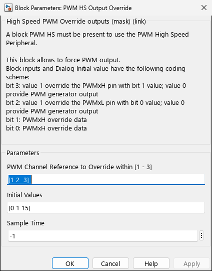
Screenshots taken with chip 33EP64MC506
Parameters
Override Channel Selection
| Parameter | Description | Values |
|---|---|---|
| OverrideChannels | Select which PWM channels are controlled by override | Vector of channel numbers [1 2 3 …] |
| OverrideMode | Override application mode | • Individual (per channel control) |
Override State Configuration
| Parameter | Description | Values |
|---|---|---|
| DefaultState_H | Default state for high-side outputs when override active | 0 (Low), 1 (High) |
| DefaultState_L | Default state for low-side outputs when override active | 0 (Low), 1 (High) |
| SyncMode | Synchronization with PWM timebase | • Immediate (override applied immediately) |
Block Inputs
Individual Override Mode
| Input | Type | Description |
|---|---|---|
| Override_En 1..N | boolean | Enable override for channel N (1=override active, 0=normal PWM) |
| Override_H 1..N | boolean | High-side output state when override enabled for channel N |
| Override_L 1..N | boolean | Low-side output state when override enabled for channel N |
Grouped Override Mode
| Input | Type | Description |
|---|---|---|
| Override_En | boolean | Enable override for all selected channels |
| Override_Value | uint16 | Bitfield: override state for all channels |
Block Outputs
| Output | Type | Description |
|---|---|---|
| Override_Status | uint16 | Current override register value (IOCONx.OVRDAT bits) |
| Override_Active | boolean | Indicates if any override is currently active |
Safety Considerations
⚠️ Critical Safety Guidelines
- Never enable both high and low side simultaneously unless using push-pull mode with appropriate hardware
- Always configure safe default states before enabling override
- Test override logic thoroughly on bench before motor connection
- Implement timeout protection to revert to safe state if control loop fails
- Use hardware fault inputs as primary protection; override is secondary
Recommended Safe States
| Application | Safe State | Rationale |
|---|---|---|
| Motor Drive (Half-bridge) | All outputs LOW | Prevents shoot-through, allows motor to freewheel via body diodes |
| Buck Converter | High-side OFF, Low-side ON | Maintains inductor current path, prevents voltage spikes |
| Boost Converter | High-side OFF, Low-side ON | Prevents output overvoltage |
| Push-Pull Transformer | Both sides OFF | Prevents transformer saturation |
Features
- Direct control of PWM output pins (PWMxH and PWMxL)
- Individual or grouped override control
- Override enable/disable per channel
- Synchronization with PWM generator (optional)
- Support for safe state configuration
- Runtime override value modification
Examples
Example 1: Emergency Shutdown
% Configuration:
% OverrideChannels = [1 2 3];  % All motor phases
% OverrideMode = 'Grouped';
% DefaultState_H = 0;           % All high-sides OFF
% DefaultState_L = 0;           % All low-sides OFF
% SyncMode = 'Immediate';       % Fastest response

% Model logic:
% Connect emergency stop button -> Override_En input
% When E-stop pressed: all outputs forced LOW immediately

% Simulink implementation:
%  [E_Stop] ──→ [Override_En]
%  [0]      ──→ [Override_Value]  % All bits 0 = all outputs LOW
Example 2: Diagnostic Mode - Individual Phase Test
% Configuration:
% OverrideChannels = [1 2 3];
% OverrideMode = 'Individual';

% Test sequence (executed by state machine):
% 1. Override PWM1: High-side ON, Low-side OFF
% 2. Measure current
% 3. Override PWM1: High-side OFF, Low-side ON
% 4. Measure current
% 5. Repeat for PWM2, PWM3

% Block inputs:
%  Override_En_1 = test_active && (phase == 1);
%  Override_H_1 = test_state == HIGH_SIDE_TEST;
%  Override_L_1 = test_state == LOW_SIDE_TEST;
Example 3: Custom Commutation Pattern (BLDC)
% For 6-step BLDC commutation with hall sensors:
% OverrideChannels = [1 2 3];
% OverrideMode = 'Grouped';

% Commutation table (hall sensor state -> override value):
% Hall = 001: PWM1H=1, PWM1L=0, PWM2H=0, PWM2L=1, PWM3H/L=0
% Hall = 010: ...

commutationTable = [
    bin2dec('000000'),  % Hall 000 (invalid)
    bin2dec('100001'),  % Hall 001
    bin2dec('001100'),  % Hall 010
    bin2dec('101100'),  % Hall 011
    bin2dec('110010'),  % Hall 100
    bin2dec('110001'),  % Hall 101
    bin2dec('011010'),  % Hall 110
    bin2dec('000000')   % Hall 111 (invalid)
];

% Model:
%  [Hall_State] ──→ [Lookup Table] ──→ [Override_Value]
%                   (commutationTable)
%  [BLDC_Mode]  ──→ [Override_En]  % Enable override in BLDC mode
Example 4: Shoot-Through Protection
% Prevent both high and low side ON simultaneously:
% OverrideChannels = [1 2 3];
% OverrideMode = 'Individual';
% SyncMode = 'Synchronized';  % Avoid glitches

% Protection logic (for each channel):
%  if (PWM_H_command && PWM_L_command)  % Illegal state
%      Override_En = 1;
%      Override_H = 0;
%      Override_L = 0;
%  else
%      Override_En = 0;  % Normal PWM operation
%  end
Troubleshooting
Override Not Working
Possible Causes:
- Fault input active (fault has higher priority than override)
- Incorrect channel numbering (check enabled channels in PWM_HighSpeed block)
- Override disabled in IOCONx register (check TLC code generation)
Unexpected Output States
Solutions:
- Verify Override_Value bitfield mapping matches hardware PWM numbering
- Check for conflicts with PWM output polarity settings (PENH/PENL in IOCONx)
- Ensure synchronized mode is used if immediate override causes glitches
Shoot-Through During Override Transition
Symptom: Momentary short circuit during override enable/disable Solutions:
- Use synchronized mode (SyncMode = ‘Synchronized’)
- Implement software dead-time in override logic
- Sequence override transitions: first disable old state, wait dead-time, then enable new state
Implementation Details
Hardware Registers
The override block configures the following registers:
| Register | Bits | Purpose |
|---|---|---|
| IOCONx | OVRENH, OVRENL | Enable override for high and low outputs |
| IOCONx | OVRDAT[1:0] | Override data (output pin states when override enabled) |
| IOCONx | OSYNC | Override synchronization (0=immediate, 1=sync with PWM) |
Override Priority
When multiple control mechanisms are active, the priority order is:
- Fault override (highest priority) - hardware fault forces outputs to safe state
- Manual override (this block) - software controlled override
- Normal PWM (lowest priority) - PWM generator output
Related Blocks
MCHP_PWM_HighSpeed - Main PWM block (required for override block to function)
MCHP_PWM - Standard PWM (has built-in OVDCON register control)
MCHP_PWM_SAM7x_Override - Override block for SAM7x devices
MCHP_Comparator - Hardware fault generation
[Peripheral Block Overview](../
dsPIC33F/EP Family Reference Manual - PWM Override Control
dsPIC33C Family Reference Manual - Output Override and Polarity Control