PWM SAM7x


Overview
The PWM SAM7x block configures the Pulse Width Modulation Controller (PWMC) peripheral on SAME7x/SAMS7x/SAMV7x microcontrollers. Each controller (PWM0 or PWM1) supports up to 4 independent PWM channels with complementary high/low outputs, programmable dead-time, and fault protection.
When to use:
- Motor control and power conversion on SAM E7x, SAM S7x, SAM V7x, or SAM RH71 devices
- Applications requiring up to 4 complementary PWM channels per controller (8 total with PWM0+PWM1)
- Push-pull mode for half-bridge topologies
- PWM event line triggers for ADC synchronization (8 comparators)
When NOT to use:
- SAM E5x, SAM C2x, or SAM D2x devices → use TCC PWM
- dsPIC devices → use PWM , PWM HighSpeed , or PWM HS FEP depending on family
Key Features:
- Up to 4 PWM channels per controller with complementary outputs (PWMH/PWML)
- Left-aligned or center-aligned PWM generation
- Independent or synchronized channel operation
- Programmable dead-time insertion (8-bit resolution per channel)
- 8 fault input sources with configurable protection
- Event line triggers for ADC synchronization (8 comparators)
- Push-pull mode for half-bridge topologies
- Individual signal polarity inversion
Block Dialog
SAME70Q21B - UFBGA144Ports
Inputs
| Port | Type | Condition | Description |
|---|---|---|---|
| Period | scalar | BlockInput_Period ≠ Not a block input | PWM period control (updates all channels) |
| DutyCycle[N] | scalar or vector | BlockInput_DutyCycle ≠ Not a block input | Duty cycle for enabled channels (N = channel indices or vector) |
| DeadTimeH[N] | scalar or vector | BlockInput_DeadTime ≠ Not a block input | Dynamic high-side dead-time per channel |
| DeadTimeL[N] | scalar or vector | BlockInput_DeadTime ≠ Not a block input | Dynamic low-side dead-time per channel |
Input Scaling:
Uint raw input: Direct 16-bit register value (0 to PWMxmax variable)FP [0 1]: 0.0 = 0% duty, 1.0 = 100% dutyFP [-1 1]: -1.0 = 0%, 0.0 = 50%, 1.0 = 100%FP physical scaling (s): Absolute time in seconds
Outputs
The block has no outputs. PWM signals are generated directly on configured pins.
Register Configuration (click to expand)
Parameters
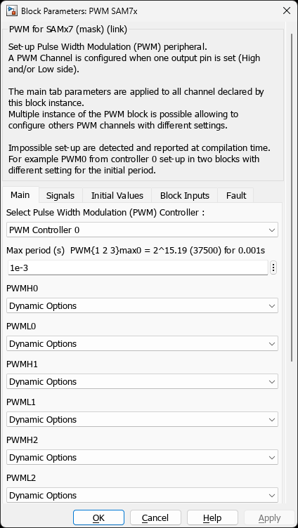
Main Tab
| Parameter | Variable | Type | Description |
|---|---|---|---|
| PWM Controller | PWMx | popup | Select PWM Controller 0 or PWM Controller 1 |
| Max period (s) | MaxPeriod_s | scalar | Maximum PWM period in seconds. Determines resolution via automatic prescaler selection. Workspace variables PWMxmaxN are created (N = channel number). |
| Pin PWMH0 | PWM0_pinH0 | popup | High-side output pin for channel 0 (dynamic pin selection per chip) |
| Pin PWML0 | PWM0_pinL0 | popup | Low-side output pin for channel 0 |
| Pin PWMH1 | PWM0_pinH1 | popup | High-side output pin for channel 1 |
| Pin PWML1 | PWM0_pinL1 | popup | Low-side output pin for channel 1 |
| Pin PWMH2 | PWM0_pinH2 | popup | High-side output pin for channel 2 |
| Pin PWML2 | PWM0_pinL2 | popup | Low-side output pin for channel 2 |
| Pin PWMH3 | PWM0_pinH3 | popup | High-side output pin for channel 3 |
| Pin PWML3 | PWM0_pinL3 | popup | Low-side output pin for channel 3 |
| Center aligned | PWM_Centered | checkbox | Enable center-aligned PWM (up-down counting). When disabled, uses left-aligned (up counting) mode. |
| Synchronized (with PWM0) | PWM_SyncWithPWM0 | checkbox | Synchronize all enabled channels with channel 0. Period is controlled by PWM0, duty cycles remain independent. |
| Push-Pull Mode | PushPull_Mode | checkbox | Enable push-pull output mode for half-bridge applications. Changes complementary behavior. |
| Block output sample time | SampleTime | scalar | Block execution sample time (typically -1 for inherited) |
Note: Pin selections labeled PWM1_pinHx/PWM1_pinLx are visible when PWM Controller 1 is selected. Each controller has its own set of 8 pins (4 channels × H/L sides).
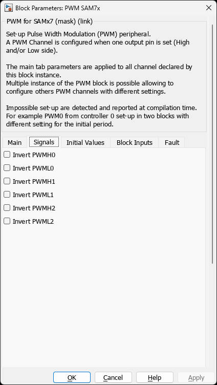
Signals Tab
| Parameter | Variable | Type | Description |
|---|---|---|---|
| Invert PWMH0..3 | invert_PWMH0 to invert_PWMH3 | checkbox | Invert high-side output polarity (one per enabled channel) |
| Invert PWML0..3 | invert_PWML0 to invert_PWML3 | checkbox | Invert low-side output polarity (one per enabled channel) |
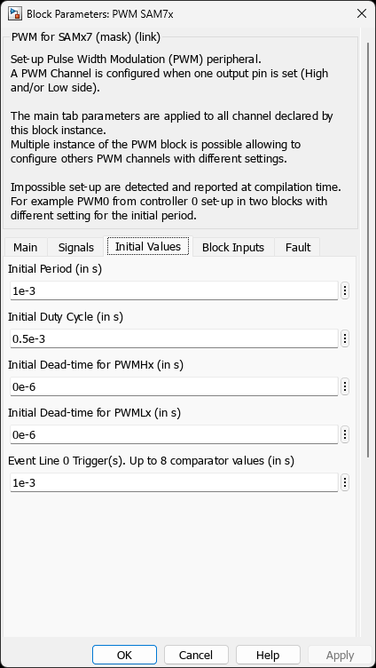
Initial Values Tab
| Parameter | Variable | Type | Description |
|---|---|---|---|
| Initial Period (in s) | InitPeriod_s | scalar or vector | Initial PWM period at startup. Scalar applies to all channels; vector allows per-channel values. |
| Initial Duty Cycle (in s) | InitDutyCycle_s | scalar or vector | Initial duty cycle in seconds (not percentage). Scalar or per-channel vector. |
| Initial Dead-time for PWMHx (in s) | InitDeadTimeH_s | scalar or vector | Dead-time applied when transitioning high-side output (max 4095 ticks, ~26.6 µs at 150 MHz) |
| Initial Dead-time for PWMLx (in s) | InitDeadTimeL_s | scalar or vector | Dead-time applied when transitioning low-side output |
| Event Line 0 Trigger(s) | InitEventLine0_ComparatorValue_s | scalar or vector | Up to 8 comparator values (in seconds) to generate triggers on Event Line 0 for ADC sync |
| Event Line 1 Trigger(s) | InitEventLine1_ComparatorValue_s | scalar or vector | Up to 8 comparator values for Event Line 1 (future use) |
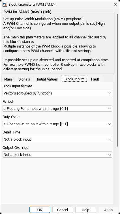
Block Inputs Tab
| Parameter | Variable | Type | Description |
|---|---|---|---|
| Block input format | BlockInput_VectorScalar | popup | Independent Scalar (one input per channel) or Vectors (grouped by function) (one vector input per function) |
| Period | BlockInput_Period | popup | Period input type: Not a block input, Uint raw input, FP [0 1], FP [-1 1], or FP physical scaling (s) |
| Duty Cycle | BlockInput_DutyCycle | popup | Duty cycle input type (same options as Period) |
| Dead Time | BlockInput_DeadTime | popup | Dead-time input type. If enabled, creates separate DeadTimeH and DeadTimeL inputs. |
| Output Override | BlockInput_OutputOverride | popup | Override control (currently Not a block input - use PWM SAM7x Override block) |
Fault Tab
| Parameter | Variable | Type | Description |
|---|---|---|---|
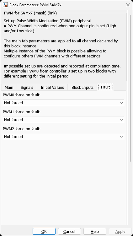
| PWM0..3 force on fault | Fault_FPV0 to Fault_FPV3 | popup | Output state on fault: Not forced, PWM H/L -> 00/ZZ/11/01/10/1Z/0Z/Z1/Z0, PWM H -> 0-/1-/Z-, PWM L -> -0/-1/-Z (Z = high impedance) |
| PWMFI0..2 input pin | Fault_Input0 to Fault_Input2 | popup | Fault pin trigger: does nothing, trig on level high, trig on level low |
| PWMFI0..2 is filtered | Fault_Input0_FFIL to Fault_Input2_FFIL | checkbox | Enable glitch filter on fault input |
| Oscillator fault | Fault_Input3 | popup | Trigger on oscillator failure |
| ADC (AFEC0/1) | Fault_Input4, Fault_Input5 | popup | Trigger from ADC comparison result |
| Analog Comparator (ACC) | Fault_Input6 | popup | Trigger from analog comparator |
| Timer 0 | Fault_Input7 | popup | Trigger from Timer/Counter 0 overflow |
Register Configuration
The block configures the following PWMC peripheral registers:
Clock Configuration (Start function)
- PWM_CLK: Prescaler (PREA/DIVA for Clock A, PREB/DIVB for Clock B)
- Selects from {1, 2, 4, 8, 16, 64, 256, 1024} divisors
- Linear divider (DIVA/DIVB) 1–255
- Optimized to achieve maximum resolution at requested max period
Channel Configuration (per enabled channel)
PWM_CMRx: Channel Mode Register
CPRE: Clock prescaler selection (Clock A/B or MCK direct)CALG: 0=left aligned, 1=center alignedPPM: Push-pull mode enableDTE: Dead-time enableDTHI/DTLI: Dead-time output inversion
PWM_CPRDx: Channel Period Register (16-bit)
PWM_CDTYx: Channel Duty Cycle Register (16-bit)
PWM_DTx: Dead Time Register (DTH[15:8], DTL[7:0])
Synchronization (if enabled)
- PWM_SCM: Synchronous Channels Mode
SYNC0..3: Synchronize channels to PWM0 period
Fault Protection (if configured)
- PWM_FPE: Fault Protection Enable (per channel, 8 fault sources)
- PWM_FPV: Fault Protection Value (output states per channel)
- PWM_FMR: Fault Mode Register (polarity, mode, filter per fault)
- PWM_ETRG1/2: External Trigger (recoverable fault on sources 1/2)
Event Line Triggers (if comparator values set)
- PWM_CMPVx: Comparison Value Registers (8 comparators)
- PWM_ELMR[0]: Event Line Mode Register (comparator to line mapping)
Dynamic Updates (Outputs function)
- PWM_CPRDUPDx: Period update (buffered, synchronized)
- PWM_CDTYUPDx: Duty cycle update (buffered)
- PWM_DTUPDx: Dead-time update (buffered)
- PWM_SCUC: Synchronous Channels Update Control (triggers buffered updates)
Notes
Multiple Block Instances
Multiple instances of the PWM SAM7x block can control different channels of the same controller, but shared parameters (clock, center-aligned mode, synchronization) must match exactly or a compilation error will occur. The TLC code validates consistency using MchpLocal2Global().
Synchronized Mode Restrictions
When PWM_SyncWithPWM0 = on:
- Channel 0 period controls all synchronized channels
- Individual period updates are ignored
- Duty cycle remains independently controllable per channel
- All synchronized channels must use the same clock source
Dead-Time Limitations
- Dead-time resolution: 8 bits (0–255 prescaler ticks)
- Maximum dead-time depends on prescaler (e.g., 26.6 µs at 150 MHz with DIV1)
- Applied symmetrically (same dead-time for rise/fall transitions)
- Configured per channel, not per output
Clock Resolution Trade-off
The block automatically selects prescaler (PREA, DIVA) to achieve:
- Maximum period ≤ requested
MaxPeriod_s - Maximum PWM resolution (16-bit counter utilization)
Higher MaxPeriod_s → coarser duty cycle steps. For 20 kHz @ 150 MHz: ~7500 steps.
Device Support
- SAM E70 (SAME70Q19/20/21, SAME70N19/20/21, SAME70J19/20/21)
- SAM S70 (SAMS70Q19/20/21, SAMS70N19/20/21, SAMS70J19/20/21)
- SAM V70 (SAMV70Q19/20, SAMV70N19/20, SAMV70J19/20)
- SAM V71 (SAMV71Q19/20/21, SAMV71N19/20/21, SAMV71J19/20/21)
- SAM RH71 (SAMRH71F20)
All devices feature two independent PWM controllers (PWM0, PWM1) with 4 channels each.
Examples
Three-Phase Motor Control (Center-Aligned)
% SAME70 FOC motor drive, 20 kHz PWM, 1 µs dead-time
PWMx = 'PWM Controller 0';
MaxPeriod_s = 1/20e3;  % 50 µs = 20 kHz
PWM_Centered = 'on';
PWM_SyncWithPWM0 = 'on';

% Enable 3 channels
PWM0_pinH0 = 'PA11 / Pin[64]';  % Phase U
PWM0_pinL0 = 'PD24 / Pin[55]';
PWM0_pinH1 = 'PA2 / Pin[93]';   % Phase V
PWM0_pinL1 = 'PA20 / Pin[22]';
PWM0_pinH2 = 'PA13 / Pin[42]';  % Phase W
PWM0_pinL2 = 'PA16 / Pin[45]';

InitPeriod_s = 1/20e3;
InitDutyCycle_s = [25e-6, 25e-6, 25e-6];  % 50% initial
InitDeadTimeH_s = 1e-6;
InitDeadTimeL_s = 1e-6;

% Runtime duty cycle control
BlockInput_DutyCycle = 'a Floating Point input within range [0 1]';
BlockInput_VectorScalar = 'Vectors (grouped by function)';

% Connect 3-element duty cycle vector from FOC algorithm
Single-Phase with ADC Synchronization
% Sync ADC sampling to PWM peak (for current sensing)
PWMx = 'PWM Controller 0';
MaxPeriod_s = 100e-6;  % 10 kHz
PWM0_pinH0 = 'PA11 / Pin[64]';
PWM0_pinL0 = 'PD24 / Pin[55]';

% Trigger ADC at 90% of period (valley sampling)
InitEventLine0_ComparatorValue_s = 90e-6;

% Enable ADC block with "PWM Event Line 0" trigger source
Fault Protection with Over-Current Trip
% Set all outputs to high-Z on AFEC0 fault (analog comparator result)
Fault_Input4 = 'trig a fault';  % AFEC0
Fault_Input4_FFIL = 'on';       % Filter glitches

Fault_FPV0 = 'PWM H/L -> ZZ';   % High impedance
Fault_FPV1 = 'PWM H/L -> ZZ';
Fault_FPV2 = 'PWM H/L -> ZZ';

% Configure AFEC0 to compare current sense ADC against threshold
Related Blocks
- PWM SAM7x Override — Manual output control and emergency shutdown
- MCHP_ADC_SAM — ADC with PWM event line synchronization
- MCHP_QEI_SAM — Quadrature encoder for motor feedback