PWM SAM7x Override


Block Dialog
SAME70Q21B - UFBGA144Overview
The PWM SAM7x Override block provides direct control over PWM output pins by writing to the PWM Controller’s Output Override registers (PWM_OS, PWM_OSS, PWM_OSC, PWM_OOV). This allows forcing specific logic states on PWMH/PWML pins independently of the PWM waveform generator.
When to use:
- Emergency shutdown and safety state enforcement on SAM7x PWM outputs
- Diagnostic testing and individual phase/gate verification
- Custom commutation patterns for special motor types
- Active short-circuit braking
When NOT to use:
- Primary PWM generation → use PWM SAM7x block
- Override on dsPIC33C/E → use PWM HighSpeed Override
- SAM E5x/C2x devices → use pattern generator in TCC PWM
Use cases include:
- Emergency shutdown: Immediate safe-state enforcement on fault detection
- Diagnostic testing: Individual phase/gate verification before motor startup
- Custom commutation patterns: Software-generated sequences for special motor types
- Active short-circuit braking: Controlled short of motor windings
The override operates through bitfield registers where each bit corresponds to one PWM output. Updates can be immediate or synchronized to the PWM period boundary to avoid glitches.
Ports
Inputs
| Port | Type | Condition | Description |
|---|---|---|---|
| Override set/clr | uint32 | Input_PWM_OS = on | Direct write to PWM_OS register. Bitfield: 1=override, 0=PWM. Updates immediately. |
| Override set | uint32 | Input_PWM_OSS = on | Write to PWM_OSS (or PWM_OSSUPD if sync enabled). Sets bits to 1 only (does not clear). |
| Override clr | uint32 | Input_PWM_OSC = on | Write to PWM_OSC (or PWM_OSCUPD if sync enabled). Clears bits to 0 only (does not set). |
| output values | uint32 | Input_PWM_OOV = on | Direct write to PWM_OOV register. Bitfield: output pin logic levels when override is active. |
Outputs
The block has no outputs. Override state is reflected directly on PWMH/PWML pins.
Parameters
Main Tab
| Parameter | Variable | Type | Description |
|---|---|---|---|
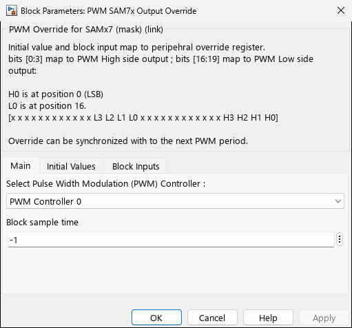
| PWM Controller | PWMx | popup | Select PWM Controller 0 or PWM Controller 1 (must match associated PWM SAM7x block) |
| Block sample time | SampleTime | scalar | Execution rate (typically -1 for inherited, or match PWM block rate) |
Initial Values Tab
| Parameter | Variable | Type | Description |
|---|---|---|---|
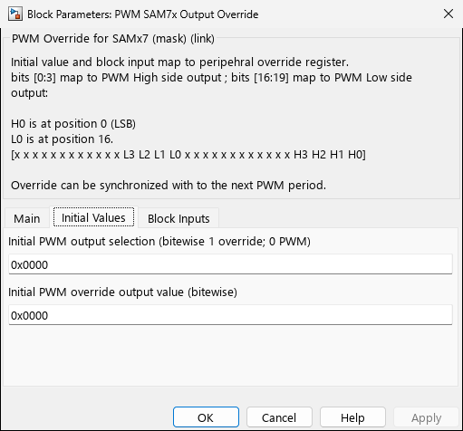
| Initial PWM output selection | Init_PWM_OS | hex string | Bitfield: 1=override active, 0=PWM generator controls output. Format: 0xHHHH (e.g., 0x0011 overrides H0/L0) |
| Initial PWM override output value | Init_PWM_OOV | hex string | Bitfield: output state when override is active. 1=high, 0=low. |
Block Inputs Tab
| Parameter | Variable | Type | Description |
|---|---|---|---|
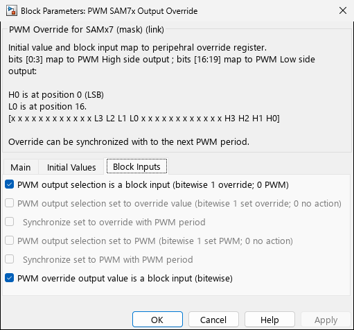
| PWM output selection is a block input | Input_PWM_OS | checkbox | Enable Override set/clr input port (PWM_OS register: immediate override on/off control) |
| PWM output selection set to override value | Input_PWM_OSS | checkbox | Enable Override set input port (PWM_OSS register: set-only operation) |
| ↳ Synchronize set to override with PWM period | Input_PWM_OSSUPD | checkbox | Use PWM_OSSUPD register (synchronized update on next period) instead of PWM_OSS |
| PWM output selection set to PWM | Input_PWM_OSC | checkbox | Enable Override clr input port (PWM_OSC register: clear-only operation) |
| ↳ Synchronize set to PWM with PWM period | Input_PWM_OSCUPD | checkbox | Use PWM_OSCUPD register (synchronized update) instead of PWM_OSC |
| PWM override output value is a block input | Input_PWM_OOV | checkbox | Enable output values input port (PWM_OOV register: override pin states) |
Input Configuration Notes:
Input_PWM_OSprovides full control (set/clear in one register). When enabled,Input_PWM_OSSandInput_PWM_OSCare disabled.Input_PWM_OSSandInput_PWM_OSCallow independent set/clear operations (useful for state machines).- Synchronized updates (
OSSUPD/OSCUPD) prevent glitches by deferring changes to period boundary.
Bitfield Mapping
The override registers use the following bit positions for each PWM channel:
| Bit Position | Output | Description |
|---|---|---|
| 0 | PWMH0 | Channel 0 high-side |
| 1 | PWMH1 | Channel 1 high-side |
| 2 | PWMH2 | Channel 2 high-side |
| 3 | PWMH3 | Channel 3 high-side |
| 16 | PWML0 | Channel 0 low-side |
| 17 | PWML1 | Channel 1 low-side |
| 18 | PWML2 | Channel 2 low-side |
| 19 | PWML3 | Channel 3 low-side |
Example bitfields:
% Override H0 and L0 (channel 0 both sides):
Override_Bits = 0x00010001;  % Bits 0 and 16

% Force H0=1, L0=0 (active high-side, inactive low-side):
Output_Bits = 0x00000001;    % Bit 0 set, bit 16 clear

% All high-sides to safe state (low):
Override_Bits = 0x0000000F;  % Bits 0-3
Output_Bits   = 0x00000000;  % All clear
Register Configuration
The block writes the following PWMC peripheral registers:
Initialization (Start function)
PWMx_REGS->PWM_OS  = Init_PWM_OS;   // Initial override enable (if > 0)
PWMx_REGS->PWM_OOV = Init_PWM_OOV;  // Initial override output values
Runtime Updates (Outputs function)
Depending on enabled inputs:
// Direct override control (immediate)
if (Input_PWM_OS)
    PWMx_REGS->PWM_OS = input_value;

// Set-only control (immediate or synchronized)
if (Input_PWM_OSS && !Input_PWM_OSSUPD)
    PWMx_REGS->PWM_OSS = input_value;       // Immediate
else if (Input_PWM_OSS && Input_PWM_OSSUPD)
    PWMx_REGS->PWM_OSSUPD = input_value;    // Sync to period

// Clear-only control (immediate or synchronized)
if (Input_PWM_OSC && !Input_PWM_OSCUPD)
    PWMx_REGS->PWM_OSC = input_value;
else if (Input_PWM_OSC && Input_PWM_OSCUPD)
    PWMx_REGS->PWM_OSCUPD = input_value;

// Output values
if (Input_PWM_OOV)
    PWMx_REGS->PWM_OOV = input_value;
Notes
Interaction with PWM SAM7x Block
- The PWM SAM7x block configures PWM waveforms, clocks, dead-time, and fault protection.
- The PWM SAM7x Override block only writes override registers (PWM_OS, PWM_OSS, PWM_OSC, PWM_OOV).
- Both blocks can coexist and control the same PWM controller simultaneously.
- Override takes precedence: when override is active (bit=1 in PWM_OS), PWM generator output is ignored.
Safety Considerations
⚠️ Risk of Shoot-Through:
- Forcing both PWMH and PWML to 1 simultaneously can destroy power stage MOSFETs.
- Always enforce software dead-time in override logic.
- Use fault protection block parameters in PWM SAM7x for hardware failsafe.
⚠️ Synchronization:
- Immediate updates (
PWM_OS,PWM_OSS,PWM_OSC) change outputs mid-period → potential voltage spikes. - Use synchronized updates (
PWM_OSSUPD,PWM_OSCUPD) for glitch-free transitions.
Register Persistence
- PWM_OS: Read-modify-write safe (holds current override state)
- PWM_OSS/OSC: Write-only set/clear (reading returns 0, use carefully)
- PWM_OOV: Read-modify-write safe
To toggle a single output without affecting others:
% Read current state
current_os = read_pwm_register('PWM_OS');
% Set bit 0 (PWMH0)
new_os = bitor(current_os, uint32(1));
Clock Requirement
The PWM peripheral clock must be enabled by the PWM SAM7x block before using override. Standalone override blocks will fail if no PWM SAM7x instance is present.
Device Support
- SAM E70 (SAME70Q/N/J 19/20/21)
- SAM S70 (SAMS70Q/N/J 19/20/21)
- SAM V70 (SAMV70Q/N/J 19/20)
- SAM V71 (SAMV71Q/N/J 19/20/21)
- SAM RH71 (SAMRH71F20)
Examples
Emergency Shutdown (Immediate)
% Kill switch: force all outputs LOW on fault signal
PWMx = 'PWM Controller 0';
Input_PWM_OS = 'on';   % Direct override control
Input_PWM_OOV = 'on';  % Control output values

% Initial state: PWM controls all outputs
Init_PWM_OS  = '0x00000000';
Init_PWM_OOV = '0x00000000';

% In Simulink model:
% Connect fault_signal -> Override set/clr input
%   fault_signal = 0 -> Normal PWM operation
%   fault_signal = 0x0003000F -> Override all, outputs LOW

% Matlab Function block:
function [override_bits, output_bits] = emergency_stop(fault)
    if fault
        override_bits = uint32(hex2dec('0003000F')); % Override H0-H3, L0-L3
        output_bits   = uint32(0);                   % All outputs LOW
    else
        override_bits = uint32(0);                   % PWM generator controls
        output_bits   = uint32(0);
    end
end
Diagnostic Pattern (Synchronized)
% Step through phases one at a time (synchronized to avoid glitches)
PWMx = 'PWM Controller 0';
Input_PWM_OSS = 'on';
Input_PWM_OSSUPD = 'on';  % Sync to period
Input_PWM_OOV = 'on';

% Stateflow chart cycles through:
% State 1: H0=1, L0=0, others off  -> 0x00000001 override, 0x00000001 output
% State 2: H1=1, L1=0, others off  -> 0x00020002 override, 0x00000002 output
% State 3: H2=1, L2=0, others off  -> 0x00040004 override, 0x00000004 output
Active Short Braking
% Short motor windings for rapid deceleration (all low-sides ON)
PWMx = 'PWM Controller 0';
Input_PWM_OS = 'on';
Input_PWM_OOV = 'on';

% MATLAB Function:
function [override, outputs] = brake_control(enable_brake)
    if enable_brake
        override = uint32(hex2dec('00070007')); % Override H0-2, L0-2
        outputs  = uint32(hex2dec('00070000')); % H0-2=OFF, L0-2=ON
    else
        override = uint32(0);
        outputs  = uint32(0);
    end
end
Hybrid PWM + Override (Independent Control)
% Override L0 for custom pattern, PWM controls H0-H2
PWMx = 'PWM Controller 0';
Input_PWM_OSS = 'on';      % Only set override (not clear)
Input_PWM_OOV = 'on';

% Initial: override only L0
Init_PWM_OS  = '0x00010000';  % Bit 16 (PWML0)
Init_PWM_OOV = '0x00000000';  % L0 starts LOW

% Runtime: toggle L0 via Override set input
% PWM block controls H0-H2 duty cycles normally
Related Blocks
- PWM SAM7x — Main PWM configuration and waveform generation
- MCHP_GPIO_Output — Alternative for simple on/off control without PWM peripheral