Interrupt


When to use:
When to use:
- Hardware event must trigger Simulink subsystem (ADC done, UART RX, encoder overflow)
- Need lowest latency response to peripheral event (faster than polling)
- PWM-synchronized control loop (ADC interrupt after PWM trigger)
- Asynchronous communication (UART/SPI/I2C receive events)
- Extending encoder range with overflow/underflow interrupts
When NOT to use:
- Timer-based periodic tasks suffice — use Simulink sample times instead
- Polling peripheral status is fast enough for application timing
- Adding complexity without latency benefit — interrupts add overhead
- Peripheral block does not define interrupt source (check dropdown list)
Block Dialog
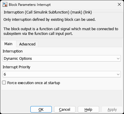
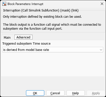
33AK512MPS512Parameters
Interrupt Selection
| Parameter | Variable | Description | Values |
|---|---|---|---|
| Interruption | Interruption | Select interrupt source from a dynamic list. The list contains, in order: (1) Class A — Driver-Owned and Class B — Peripheral-Exposed entries declared by peripheral blocks present in the model, then (2) a --- Chip Interrupt Vectors --- separator, then (3) Class C — Raw Chip Vectors read from the chip’s IVT database. See Interrupt Sources below. | • Not defined | • peripheral-declared entries (e.g. UART1 RX, ADC1 Ch0 Data Ready, QEI1POS, T2) | • --- Chip Interrupt Vectors --- | • raw chip vectors (e.g. [Timer] Timer 5 Interrupt, [CAN] CAN1 Error) |
| Interrupt Priority | IntPriority | Interrupt priority level. Editable for Class B and Class C entries. Locked (read-only) for Class A entries — the priority is owned by the declaring peripheral block (CN, SPI / I2C bus sequence, Comparator, …). Higher number = higher priority on dsPIC/PIC32; 0 = highest on ARM. | 1-7 (dsPIC) | 1-7 (PIC32) | 0-15 (ARM - 0=highest) |
| Disable FPU Context Save | FPUNoSave | (PIC32 with FPU only) Disable automatic FPU context save if ISR does not use floating-point operations (optimization). | on / off |
| Execute at Startup | StartupExecute | Execute subsystem once during initialization (before first interrupt). | on / off |
Changed in v3.63.x — The legacy fire-every-step fallback has been removed. A triggered subsystem connected to an Interrupt block whose source is never raised at run-time is now reported as a build-time configuration error instead of silently firing at the model base rate. If an older model relied on that behaviour, connect the subsystem to a Timer-based trigger instead, or mark
StartupExecute=onwhen a one-shot initialisation is all that is needed. The Change Notification (CN) callback also emits a warning whenEVT_ENis empty but at least one channel is configured, to catch the same misconfiguration on CN-driven interrupts.
Timing Configuration
| Parameter | Variable | Description | Use Case |
|---|---|---|---|
| Time Source | Triggered_Sub_TimeSource | Timing reference for triggered subsystem sample time. | • Base rate: Synchronized to model base rate | • Periodic trigs: User-specified period | • Hardware timer: Dedicated timer resource |
| Trigger Period | TrigsPeriod | (Periodic trigs mode) Subsystem sample time when using periodic trigger mode. | Any value matching trigger rate (e.g., 100e-6 for 10 kHz) |
| Timer Resolution | TIMER_Resolution | (Hardware timer mode) Select timer prescaler for desired resolution and max period. | Dynamic list based on device: | • dsPIC: 1, 8, 64, 256 prescalers | • PIC32: 1, 2, 4, 8, 16, 32, 64, 256 | • SAM: 8, 32, 128 divisors |
Interrupt Sources
The Interruption popup is built dynamically every time the dialog opens. It is populated from two passes over the model:
- Phase 1 — Peripheral declarations. Every block whose mask exposes a non-empty
MCHP_USER_INTERRUPTSparameter contributes one or more entries (ADC, PWM, UART, QEI, Timer Config, CN, Comparator, I2C/SPI sequence-Interrupt actions, …). - Phase 2 — Chip IVT database. After the peripheral pass, the callback queries
MCHP_Fun.MCHP_IVT_FromDB(chipName)and appends every IVT vector defined for the actual target chip that has not already been claimed in Phase 1. These appear under the popup separator--- Chip Interrupt Vectors ---.
What ends up in the Interrupt block dialog therefore falls into three classes with very different responsibilities for the user.
The three classes of interrupts
| Class | Popup label looks like | Where it comes from | Priority field | Wiring an Interrupt block to it | What you (the user) must still do |
|---|---|---|---|---|---|
| A — Driver-Owned Interrupt | CN1, SPI1 …, I2C1 …, CMP1r, (future: UART1 RX) | A peripheral block declares the entry with Priority(N) where N ≥ 0 | Locked / read-only — the priority is owned by the declaring peripheral block (CN, SPI, I2C, …). | Optional and chained — if you wire one, your triggered subsystem runs after the peripheral driver has finished servicing the interrupt, inside the same ISR. The Interrupt block emits no vector of its own; it only contributes the subsystem body, which the driver invokes (Tier 1 inline for CN, Tier 3 hardcoded #ifdef Flag_… call-site for SPI/I2C/Comparator). If you do not wire one, the driver-only ISR runs as-is. | Nothing for the flag handshake. The driver’s ISR clears xxIF, reads any required register, and then — if you wired an Interrupt block — calls your subsystem. |
| B — Peripheral-Exposed Interrupt | ADC1 Ch0 Data Ready, QEI1POS, T2, PWM1 Period, … (no […] prefix) | A peripheral block declares the entry with Priority(-1) | Editable | Wiring an Interrupt block is what enables the interrupt. The Interrupt block emits a full __attribute__((interrupt)) vector that① sets xxIP to your priority,② sets xxIE = 1,③ sets the Config_BitSet (e.g. QEI1CONbits.CNTERIE = 1) if the peripheral block provided one,④ on entry reads RegisterReadClear (captured into MCHP_ISR_<IE>_ReadValue),⑤ writes xxIF = 0,⑥ then calls your triggered subsystem. Without a wired Interrupt block, the entry is dormant — no IE bit is set, no ISR is generated. | Nothing for the basic flag handshake. Only application-specific work (read FIFO words, advance state machine, etc.). |
| C — Raw Chip Vector | [GROUP] Description (group tag from the chip database, e.g. [Timer] Timer 5 Interrupt, [DMA] DMA Channel 3, [CAN] CAN1 Error) | The chip’s IVT database — no peripheral block declared it | Editable | Same auto-generated vector as Class B (xxIP, xxIE = 1, xxIF = 0, optional RegisterReadClear if the database provides one, then your subsystem call). | Anything beyond IE/IF/IP. The peripheral itself is not configured by any MCHP block — you must initialise it by writing the relevant SFRs in your model (typically with the Reg Write block or a custom S-Function), enable any sub-event flags, drain any FIFO, etc. The Interrupt block only handles the vector wrapper. |
Classes A and B both stem from MCHP_USER_INTERRUPTS; their distinction is only the value of Priority. Class C bypasses MCHP_USER_INTERRUPTS entirely.
Class A — chaining a user subsystem after the driver. This is the deliberate “hook” pattern: e.g. on a CN interrupt, the CN block writes the ISR (debounce, edge-detect, register read), and your wired Interrupt subsystem runs at the end of that same ISR — you only see the post-processed event. Same for SPI / I2C sequence-step interrupts, Comparator, UART RX/TX (Circular Buffer / DMA), DMA, and QEI in turn-counting mode. The chaining is automatic; the only signal that an entry is Class A is the locked priority field.
Implementation tiers. The hook is realised by three slightly different code-generation paths — Tier 1 inline for CN, Tier 2 callable function via
MCHP_CallUserISRfor UART / QEI / DMA, and Tier 3 hardcoded#ifdef Flag_… / func(); / #endifcall-site for SPI / I2C / Comparator. From the user’s point of view all three are identical: pick the entry, wire the subsystem, the driver invokes it. See Driver / User ISR Coexistence below if you are authoring a new peripheral TLC.
What the block clears for you, by class
| Action | Class A (CN, SPI, I2C, Comparator, UART driver-owned, DMA, QEI turn-counting) | Class B | Class C |
|---|---|---|---|
xxIE = 1 (enable bit) | by the peripheral driver | by the Interrupt block | by the Interrupt block |
xxIP = priority | by the peripheral driver (fixed) | by the Interrupt block (user value) | by the Interrupt block (user value) |
Config_BitSet (peripheral-side enable bits, e.g. CNTERIE, ADIELbits.IE0) | by the driver (it knows what to enable) | automatic if the peripheral block provided one | not provided — IVT database has no Config_BitSet; configure via Reg Write if needed |
Read-data register (RegisterReadClear) — captures the value into MCHP_ISR_<IE_ref>_ReadValue | by the driver’s ISR (and the cleaned value is what your subsystem sees) | automatic if the peripheral block provided one | automatic if the IVT database has one for that vector; otherwise omitted |
xxIF = 0 (clear interrupt flag) | by the driver’s ISR | automatic (always) | automatic (always) |
| Other peripheral SFRs (clear status, advance FIFO, ack errata, …) | by the driver before chaining your subsystem | by your subsystem code if needed | by your subsystem code, every time |
| Order in which your subsystem runs | after all of the above (driver hands you a clean event) | after xxIF=0 and RegisterReadClear, but before any peripheral-specific cleanup | after xxIF=0, you do the rest |
In other words: you almost never have to clear xxIF yourself — the Interrupt block does it on entry — unless the silicon has a separate sub-event flag that the IVT database does not surface. Class A: nothing to do, the driver gives you a post-processed event; Class B: fully managed end-to-end as long as the peripheral block declared its RegisterReadClear; Class C: may need extra clears that you have to add to the subsystem.
How peripherals declare interrupts — MCHP_USER_INTERRUPTS
Class A and Class B entries both come from the MCHP_USER_INTERRUPTS hidden mask parameter. The Interrupt block’s callback scans every block in the model with a non-empty value and concatenates them into one list.
Declaration format — one or more semicolon-separated entries, each with four {…} fields:
{InterruptFlagRef}{ShortDescription}{LongDescription}{Parameters};
| Field | Purpose | Example |
|---|---|---|
InterruptFlagRef | C symbol stem of the IE bit (e.g. CN1IE, U1RX, AD1CH0). The Interrupt block writes xxIP/xxIE/xxIF from this stem. | U1RX |
ShortDescription | Label shown in the popup. | UART1 RX |
LongDescription | Tooltip / display annotation. | UART1 Receive Data Ready |
Parameters | Space-separated Name(Value) tokens — see below. A bare number is accepted as legacy shorthand for Priority(N). | VectorName(U1RXInterrupt) Priority(-1) RegisterReadClear(U1RXREG) |
Parameter tokens (inside the fourth field)
| Token | Meaning |
|---|---|
VectorName(txt) | Name of the ISR vector. If empty, the peripheral driver owns the __attribute__((interrupt)) and the Interrupt block emits a callable function (Tier 1 / Tier 3 below). If non-empty, the Interrupt block emits the full __attribute__((interrupt)) vector itself (Tier 2 — typical Class B path, and also Tier 2 driver-owned). |
Config_BitSet(txt) | Extra peripheral-side enable bit to set when the Interrupt block configures the vector (e.g. QEI1CONbits.CNTERIE, ADFL0CONbits.IE). |
RegisterReadClear(txt) | Data register to read on ISR entry to clear the data-ready flag (captured into MCHP_ISR_<IE_ref>_ReadValue for use by the subsystem). |
Priority(N) | -1 ⇒ Class B (user-editable priority). N ≥ 0 ⇒ Class A (locked priority, set by the declaring peripheral). The block setting Priority is responsible for programming the IPC bits; other blocks must leave priority at -1. |
Example — Change Notification (single channel) (from MCHP_CN_Callback.m):
NewMask.Values.MCHP_USER_INTERRUPTS = ...
    ['{CN1IE}{CN1}{Change Notification - 1}{' NewMask.Values.IntPriority '};'];
The fourth field is a bare number ⇒ treated as Priority(N); VectorName is empty ⇒ Tier 1 inline (see below).
Per-interrupt clear actions (v3.1) and the Interrupt Read Value block
New in v3.63.x. For user-owned interrupts the Interrupt block now exposes an explicit, per-interrupt set of clear actions so you control exactly what the generated vector does on entry — no hidden behaviour:
Action checkbox What the ISR does on entry Bitfield Clear writes the full REGbits.field = 0write-to-clear for the cause flag (e.g.WDTbits.WDTIF,DMTbits.DMTIF) so the source flag is really cleared, not just theIFSbit.Register Read-Clear reads the data register ( RegisterReadClear) and captures the value intoMCHP_ISR_<ref>_ReadValuebefore your subsystem runs.Config Bit Set (arm bit) sets the peripheral-side enable/arm bit ( Config_BitSet) when the vector is configured.These map to the
DoClear_1..8per-interrupt UI fields; identical IF-bit causes are collapsed so a shared flag is cleared once. Models that don’t set them keep the previous automatic behaviour (backward-compatible).Interrupt Read Value block — a companion block that outputs the value captured by Register Read-Clear (
MCHP_ISR_<ref>_ReadValue) so your model can consume the data register read at ISR entry (e.g. the UART/ADC word that cleared the flag). A single definition +externis emitted (duplicate-symbol safe).
Driver / User ISR Coexistence (dsPIC / PIC32) — three tiers
When the same vector is needed by both the peripheral driver and a user-attached Interrupt block, the blockset selects one of three code-generation tiers automatically. This is an implementation detail of how Class A is realised; users do not pick it — it is fixed per peripheral.
| Tier | Trigger | What is generated | Used by |
|---|---|---|---|
| Tier 1 — Inline | VectorName empty, Priority present (numeric) | The peripheral TLC emits the ISR directly; the Interrupt block contributes its body inline at the end of the ISR. | Change Notification (CN). |
| Tier 2 — Function call | VectorName non-empty | When Priority(N≥0) (Class A): the peripheral’s driver owns the __attribute__((interrupt)) and calls MCHP_CallUserISR(IE_ref) at the end of its ISR; the Interrupt block emits a plain callable function with the subsystem body. When Priority(-1) (Class B): the Interrupt block emits the full __attribute__((interrupt)) itself. | UART, ADC, Timer, QEI, PWM events. |
| Tier 3 — Hardcoded | VectorName empty, fixed Priority(0) | Driver embeds the ISR with a hardcoded call-site; the Interrupt block only supplies the body. | SPI, I2C. |
Why this matters — declaring an interrupt in MCHP_USER_INTERRUPTS without wiring an Interrupt block is safe: it only adds an option to the dropdown. No IE bit is set and no ISR is emitted. The blockset enforces the tier rules automatically; you only need them when authoring a new peripheral TLC.
Which peripherals declare which class — quick reference
| Peripheral block | Class A entries (driver-owned, locked priority) | Class B entries (peripheral-exposed, user-priority) | Notes |
|---|---|---|---|
| CN (Change Notification) | one per enabled CN port — Tier 1 inline, user subsystem chains transparently after the CN block’s debounce/read code | none | Class A is the standard usage. |
| I2C Master / SPI Master | one per Interrupt action you place in the I2C/SPI sequence GUI — Tier 3 hardcoded #ifdef, user subsystem chains after the bus step | none | Class A is opt-in: the entry exists only because the user added an Interrupt action to the bus sequence. |
| Comparator / HS Analog Comparator | one per enabled comparator (rising / falling / any-edge variants) — Tier 3 hardcoded | none | Class A by design (legacy code-path). |
| UART Config (Simplest / polled) | none | RX, TX (one each) | User must clear xxIF if needed inside subsystem? No — the Interrupt block does it. |
| UART Config (Circular Buffer / DMA Single / DMA Circular) | RX, TX, DMA, Event vectors (driver-owned at fixed priority — Tier 2) | none | Wiring an Interrupt block chains the user subsystem after the driver has filled / drained the buffer. Priority is set by the UART block (RX_INT_PRIORITY / TX_INT_PRIORITY). |
| ADC (HS 12b dsPIC33A, HS SAR dsPIC, HS SAR PIC32) | none | one per assigned channel + one per active digital filter | The driver itself enables only one channel — the time-step trigger channel — and emits its own ISR for it. The other channels’ Class B entries are dormant until you wire an Interrupt block. Do not wire one to the trigger channel (it would collide with the driver’s scheduler ISR). |
| PWM HS / PWM HS FEP | none | one per enabled PWM channel (period / fault / current-limit / event) | All Class B — driver does not own any PWM ISR. |
| QEI | one per QEI module when the QEI block is configured for driver-side turn-counting (QEI_IntPri field visible — Tier 2) | one per QEI module when turn-counting is disabled (Priority(-1) mode) | In turn-counting mode the driver increments / decrements the software counter on each compare event; the wired user subsystem runs after that. In Priority(-1) mode the user fully owns the ISR. |
| Timer Config | none | one per configured timer | All Class B. |
Anything else exposed by the silicon — CRC, NVM, ECC, CAN error vectors, unused DMA channels, secondary timers, etc. — does not go through any peripheral block and arrives via Phase 2 as a Class C — Raw Chip Vector under the --- Chip Interrupt Vectors --- separator.
When you would actually pick a Class A entry
- CN (digital edge-detect): the CN block does the debounce / pin-state read; your subsystem reacts to the cleaned event.
- I2C / SPI sequence-step Interrupt action: you placed the
Interruptstep inside the bus sequence; your subsystem runs at that point of the transfer. - Comparator: the analog comparator block reads CMSTAT and arms the next edge; your subsystem decides what to do with the event.
For those three, Class A is the normal way to use the interrupt, not an exception.
Device-Specific Interrupt Configuration
dsPIC30F/33F/33E/33C/33A
| Feature | Configuration | Notes |
|---|---|---|
| Priority Levels | 1-7 (7 = highest) | Default is level 4 |
| Nesting | Automatic if priorities differ | Higher priority can preempt lower |
| Vector Table | Auto-managed by blockset | IVT and AIVT support |
| Context Save | W0-W15, RCOUNT, SR | Automatic register preservation |
PIC32 (MIPS)
| Feature | Configuration | Notes |
|---|---|---|
| Priority Levels | 1-7 (7 = highest) | Sub-priority 0-3 also available |
| Shadow Registers | Automatic if configured | Fast context switch (no save) |
| FPU Context | Optional save/restore | Only if FP ops used in ISR |
| Multi-Vector Mode | Enabled by blockset | Each peripheral has dedicated vector |
SAM (ARM Cortex-M)
| Feature | Configuration | Notes |
|---|---|---|
| Priority Levels | 0-15 (0 = highest) | NVIC priority grouping |
| Tail-Chaining | Automatic hardware optimization | Back-to-back ISRs without full context restore |
| Late Arrival | Hardware-managed preemption | Higher priority can preempt during stacking |
| FPU Lazy Stacking | Conditional FP context save | Only saved if FP registers used |
Timing Modes Explained
Mode 1: Derived from Model Base Rate
- Subsystem sample time = model base rate
- Timing analysis uses base rate for schedulability
- Best for interrupts synchronized with main control loop
- Example: ADC conversion complete after PWM trigger
Mode 2: Derived from Periodic Trigs
- User specifies expected interrupt rate in TrigsPeriod
- Allows timing analysis for asynchronous interrupts
- Subsystem scheduled assuming periodic behavior
- Example: UART receive (assume max message rate)
Mode 3: Hardware Timer-Based
- Dedicated timer resource automatically allocated
- Timer configured with selected prescaler
- True periodic interrupt independent of Simulink rates
- Example: Custom 1 kHz update loop
Examples
Programmatic Setup
% Add block to model
add_block('MCHP_Blockset/System Functions/Interrupt', [mdl '/ISR']);

% Configure key parameters
set_param([mdl '/ISR'], 'Interruption', 'ADC1 Interrupt');
set_param([mdl '/ISR'], 'IntPriority', '6');
Example 1: ADC Interrupt-Driven Current Loop
// PWM triggers ADC, ADC interrupt executes control loop

Simulink Model:
1. Add PWM_HS block with ADC trigger output
2. Add ADC block with interrupt enabled
3. Add Interrupt block
4. Configure interrupt block:
   Interruption: 'ADC1 - Conversion Complete'
   Triggered_Sub_TimeSource: 'is derived from model base rate'
   IntPriority: 7  (highest - critical for motor control)

5. Create triggered subsystem connected to interrupt block
6. Add current control algorithm inside subsystem

Result: Current loop executes synchronously with PWM/ADC
Example 2: UART Receive Interrupt
// Process received data asynchronously

Configuration:
   Interruption: 'UART1 - RX'
   Triggered_Sub_TimeSource: 'is derived from trigs; trigs must be periodic'
   TrigsPeriod: 1e-3  % 1 ms assumed for timing (actual rate is async)
   IntPriority: 3  (medium priority)
   StartupExecute: on  (initialize buffers)

Subsystem:
- Read UART data from peripheral block
- Parse protocol
- Update command registers
Example 3: Hardware Timer Periodic Interrupt
// Custom periodic task independent of base rate

Configuration:
   Interruption: 'User Timer1'  (created by peripheral block)
   Triggered_Sub_TimeSource: 'is derived from a hardware timer'
   TIMER_Resolution: 'Resol: 32us - MaxPer: 2.1s'  (prescaler 256)
   IntPriority: 5

Result:
- Dedicated timer allocated automatically
- Interrupt triggers at specified rate
- Independent of Simulink sample times
Example 4: QEI Position Overflow Event
// Extend encoder range with software counter

Configuration:
   Interruption: 'QEI1 - Position Counter Overflow'
   Triggered_Sub_TimeSource: 'is derived from model base rate'
   IntPriority: 6  (high - timing critical)

Subsystem Logic:
if (QEI_DIR == FORWARD)
    ExtendedPosition += 65536;
else
    ExtendedPosition -= 65536;
end
Troubleshooting
| Problem | Cause | Solution |
|---|---|---|
| Interrupt not listed | Peripheral block not in model, or peripheral disabled the channel that would declare the entry (e.g. ADC channel without an assigned pin, CN port not enabled) | Add the peripheral block, enable the relevant channel / feature. If the silicon has the vector but no peripheral block surfaces it, scroll past --- Chip Interrupt Vectors --- and pick it as a Class C Raw Chip Vector. |
| Subsystem never executes (Class A) | Selected vector does not match the actual silicon channel servicing the event, or the peripheral block disabled the source (e.g. UART set to a mode that doesn’t own that vector) | Verify in the source block (CN block, SPI/I2C sequence, Comparator, UART block, QEI block) that the driver actually generates an ISR for the picked vector and calls MCHP_CallUserISR for it. Class A subsystems run after the driver has serviced the event. |
| Subsystem never executes (Class B) | Peripheral block did not enable the underlying source (e.g. ADC channel not assigned to a pin, no PWM event configured) | Confirm in the peripheral block that the source emits an interrupt request. The Interrupt block already sets xxIE, xxIP, Config_BitSet, and clears xxIF — the missing link is the peripheral being silent. |
| Subsystem never executes (Class C) | The peripheral that drives the vector has not been initialised — no MCHP block configures it | Initialise the SFRs yourself (Reg Write block or custom S-Function), enable any sub-event flag the IVT database does not surface. |
| System hangs in ISR (Class C) | A status / sub-event flag in addition to xxIF must be cleared, but the IVT database carries no RegisterReadClear for it | Add the appropriate register clear inside the triggered subsystem. The Interrupt block clears xxIF automatically; secondary flags are your responsibility. |
| Build error / linker collision when wiring an Interrupt block to an ADC channel | You picked the ADC channel that the ADC block uses to schedule the model base rate (the time-step trigger channel) | Pick a different ADC channel, or pick the ADC trigger event from the PWM block instead of from the ADC channel. |
| Priority field grayed out | The selected entry is Class A — Driver-Owned: priority is set by the declaring peripheral (CN block, SPI/I2C bus, Comparator, future UART) | Edit priority in the peripheral block, not here. |
| Priority not working | Architecture limitation or value out of range | Check device datasheet for valid priority range. |
| FPU corruption (PIC32) | FPUNoSave enabled but FP ops in ISR | Disable FPUNoSave or remove FP operations from ISR. |
        Keep ISR execution time short - long ISRs can cause overload
        Higher priority ISRs can preempt lower priority - ensure reentrancy
        Hardware timer mode consumes one timer resource
        StartupExecute useful for initializing communication protocols
Related Blocks
- MCHP_Scheduler_Options - Multitasking scheduler configuration
- MCHP_Master - Clock and device configuration
- MCHP_ADC_Universal - ADC interrupt sources
- MCHP_PWM_HS_FEP - PWM event interrupts