Master


When to use:
- Starting ANY new MCHP Blockset model (MANDATORY — always first block)
- Changing target microcontroller or development board
- Configuring system clock frequency (crystal, PLL, internal RC)
- Setting device configuration bits (watchdog, code protection, debug pins)
When NOT to use:
- Understanding that this block is REQUIRED in every model — no exceptions
- Selecting a supported device family (800+ dsPIC/PIC32/SAM chips available)
- Verifying clock configuration achieves desired MIPS/MHz for application timing
Block Dialog
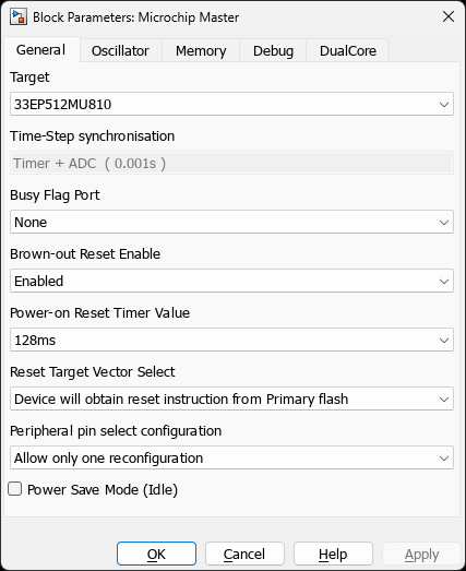
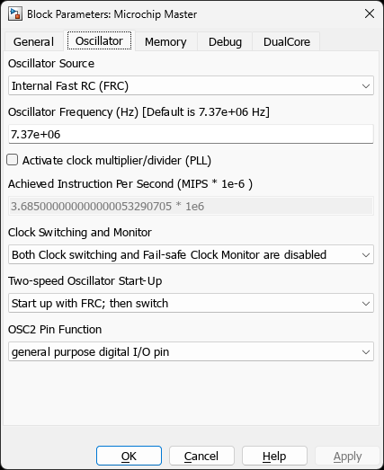
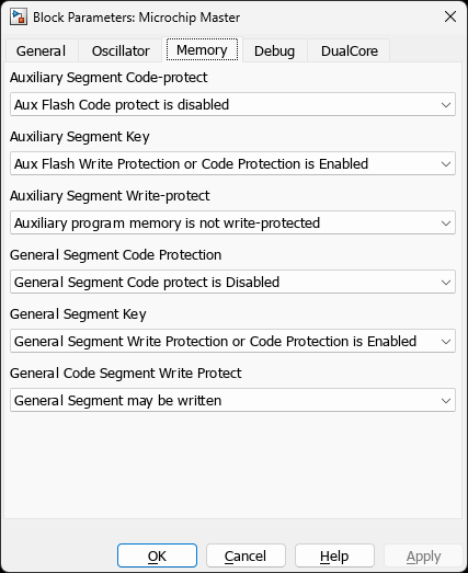
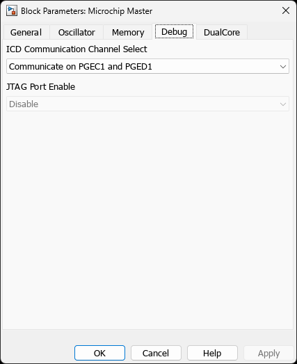
33CK256MP508Ports
Inputs: None (configuration block only)
Outputs: None (configuration block only)
This is the master configuration block that defines target device and system settings. It does not have signal ports—it provides global configuration used by all other MCHP blocks in the model.
Parameters
Target Configuration
| Parameter | Variable | Description | Values/Range |
|---|---|---|---|
| Target | PICREF | Microcontroller selection. Dynamic popup filtered by supported families with oscillator support verification. | 800+ devices (dsPIC, PIC32, SAM) |
| Package | PACKAGE | (SAM only) Package selection for ARM devices (affects pin availability). | TQFP, LQFP, QFN, etc. |
Clock Configuration
| Parameter | Variable | Description | Values/Range |
|---|---|---|---|
| Oscillator Source | OSCILLATOR_SELECT | Primary oscillator source selection. Options dynamically updated based on chip capabilities. | • Internal Fast RC (FRC) | • Internal Low Power RC (LPRC) | • Crystal/Ceramic Resonator | • External Clock (EC) | • Device-specific options |
| Crystal Frequency | QUARTZ | Crystal/resonator frequency when using external oscillator. | 0.4 MHz to 40 MHz (device-dependent) |
| Enable PLL | ACTIV_PLL | Enable Phase-Locked Loop for frequency multiplication. | on / off |
| Target MIPS | MIPS_DESIRED | Target instruction cycle frequency (FCY). Automatically calculates PLL settings. | Device-specific | Up to 200 MIPS (dsPIC33A) | Up to 300 MHz (SAME70) |
| Auxiliary Clock | ACLKCON | (dsPIC33C only) Auxiliary clock configuration for PWM and other peripherals. | AFPLLO, FRC, FOSC |
| CPU Divider | CPUDIV | (SAM Cortex-M0+ only) CPU clock divider selection. | 1, 2, 4, 8, 16, 32, 64, 128 |
| Voltage Range | VDD_range | (SAM Cortex-M0+ only) Operating voltage range (affects flash wait states). | 1.62-2.7V, 2.7-3.6V, 3.6-5.5V |
| FRC Tuning | FRC_TUNE_* | Fine-tunes the Fast RC oscillator centre frequency. Visible only when FRC (or FRC-derived PLL) is selected as the oscillator source. Grid and range are chip-dependent (see FRC / BFRC Tuning below). | Per-chip grid, or Custom expression |
| BFRC Tuning | BFRC_TUNE_Range1P5_Step0P047 | Fine-tunes the Backup FRC oscillator (dsPIC33A only). Visible only when BFRC is selected as the oscillator source. | ±1.5 % grid in 0.047 % steps, or Custom expression |
        Select oscillator source (internal RC or external crystal/clock)
        If using crystal, specify frequency in QUARTZ parameter
        Enable PLL if higher frequencies are required
        Set MIPS_DESIRED to target frequency - PLL multipliers are calculated automatically
        Block display shows achieved MIPS/MHz on the diagram
FRC / BFRC Tuning
Scope — dsPIC33F, dsPIC33E, dsPIC33C (CK / CH) and dsPIC33A only. Ignored on chips without an
OSCTUNregister.
The internal Fast RC oscillator (FRC) and, on dsPIC33A, the Backup FRC (BFRC) can be trimmed at run-time through the OSCTUN register. The Master block exposes this as a popup built from the chip’s datasheet grid, plus a Custom entry that accepts a MATLAB expression evaluated against the base workspace.
| Grid | Range | Step | Applies to |
|---|---|---|---|
Range12_Step0P375 | ±12 % (−12.000 % … +11.625 %) | 0.375 % | dsPIC33F, dsPIC33E (legacy 6-bit OSCTUN, Arch=3, non-CK/CH) |
Range1P5_Step0P047 | ±1.5 % (−1.500 % … +1.453 %) | 0.047 % | dsPIC33CK / dsPIC33CH, dsPIC33A (both FRC and BFRC) |
Register encoding — The Master block converts the selected percentage into a signed 6-bit value written to OSCTUN.TUN (FRC) or OSCTUN.BTUN (BFRC, dsPIC33A only):
- Positive percent:
TUN = round(pct / max_pos × 31)→ range0 … +31 - Negative percent:
TUN = −round(|pct| / max_neg × 32)→ range−32 … −1
The conversion is handled by MCHP_Master_OscTuneToRegister. max_pos / max_neg per grid: Range12_Step0P375 → (11.625, 12.0); Range1P5_Step0P047 → (1.45, 1.5).
Custom expression — Selecting Custom in the popup enables a sibling edit field (*_CUSTOM) that accepts any numeric MATLAB expression (including workspace variables). The expression is evaluated at build time, clamped to the grid range, and quantised to the nearest 6-bit step before being written to the register. Use this to pass calibration data loaded from, for example, a factory-test routine:
load('factory_calibration.mat', 'frcTrimPct');   % e.g. +0.235
set_param([mdl '/Master'], 'FRC_TUNE_Range1P5_Step0P047', 'Custom');
set_param([mdl '/Master'], 'FRC_TUNE_Range1P5_Step0P047_CUSTOM', 'frcTrimPct');
When to use — Temperature compensation of FRC-driven clocks, factory trim-to-target, characterising an unknown FRC drift before moving to a crystal, or deriving a calibrated baud-rate from an uncharacterised device.
Limitations — FRC / BFRC tuning does not compensate for long-term drift; for applications that require < 1 % frequency accuracy, use an external crystal or ceramic resonator via the Crystal/Ceramic Resonator oscillator source.
Fuse Configuration (Device Configuration Bits)
The Master block exposes device-specific configuration fuses extracted from Microchip XML specifications. Available fuses depend on the selected chip.
| Common Fuse Categories | Examples | Description |
|---|---|---|
| Watchdog Timer | FWDTEN, FWDTPS | Watchdog enable and prescaler settings |
| Code Protection | FCPS, FBOR | Read/write protection, boot segment protection |
| Debugging | FICD, FJTAG | ICD/JTAG enable, pin selection |
| Power Management | FBOR, FPOR | Brown-out reset, power-on reset settings |
| Peripheral Config | FIOEN, FBS | Peripheral pin select, boot segment |
Alternate Interrupt Vector Table (AIVT) & Boot Segment
On classic 16-bit dsPIC families that have an Alternate Interrupt Vector
Table (dsPIC33C/CK/CH/E/F), the Memory controls let you place the
application’s interrupt vectors in the AIVT — typically so a bootloader owns
the default vector table while the application uses the alternate one. These
controls are hidden on dsPIC33A (which uses a different IVT mechanism) and
on any device without the FSEC.AIVTDIS fuse.
| Parameter | Variable | Description |
|---|---|---|
| Enable Alternate IVT for application image | AIVT_EN | When checked, the generated startup selects the Alternate Interrupt Vector Table (INTCON2bits.AIVTEN = 1) before <model>_initialize(), so interrupts armed during initialization are serviced through the alternate (_AltXxxInterrupt) handlers. |
| Configure boot-segment size | BSLIM_EN | When checked, the boot-segment limit fuse (FBSLIM) is emitted, reserving a boot segment. |
| Boot segment limit (FBSLIM) | BSLIM_VAL | Raw 13-bit FBSLIM fuse value (hex, binary, decimal or a workspace variable). A larger value = a smaller boot segment. The AIVT lives at the start of the last boot-segment page. Range 0x0001..0x1FFE. |
Dependency — the GUI keeps these consistent automatically:
- The AIVT physically lives in the last boot-segment page, so enabling Enable Alternate IVT automatically ticks Configure boot-segment size and reveals Boot segment limit immediately (no need to click Apply).
- While Enable Alternate IVT is on, Configure boot-segment size is greyed out (disabled) — a boot segment is mandatory for the AIVT, so it cannot be unticked. Turning Enable Alternate IVT off re-enables it.
- The dependency is one-way: unchecking Enable Alternate IVT does not
clear your boot-segment choice, so a manually-configured
FBSLIMis kept. - Checking / unchecking Configure boot-segment size (when AIVT is off) shows / hides Boot segment limit immediately.
The friendly checkboxes drive the underlying
AIVTDIS/BSEN/BSLIMconfiguration fuses; the raw fuse popups are hidden to avoid conflicting settings. SetFBSLIMto exactly match the value your bootloader is built with. See the device datasheet (e.g. DS70005320 §28 for 33CK) for the boot-segment / AIVT memory map.
Dual-Core Configuration (dsPIC33CH only)
| Parameter | Description | Notes |
|---|---|---|
| Master/Slave Selection | For dsPIC33CH dual-core devices, select chip name ending with “S1” for slave core configuration. | • Master: 33CH128MP508 |
| SECONDARYIMAGE | Automatically set to slave image name when slave device is selected. | Used by build system to link secondary core code |
Build Configuration
| Parameter | Description | Set By |
|---|---|---|
| Compiler Path | Automatically detected compiler installation paths. | Auto-configured from system |
| Header Paths | Include directories for device headers. | Auto-configured from DFP |
| Linker Script | Memory map linker script selection. | Auto-selected or custom |
| Library Paths | Standard library paths (math, DSP, etc.). | Auto-configured |
External Mode
External Mode is not configured on the Master block. The communication channel is a MCHP UART Config block with its Use this UART for External Mode / PIL option enabled, and the host COM port / baud are chosen from the External Mode configuration panel on the Microchip toolstrip. See the External Mode guide. The Master block only selects the target device and clock that the rest of the model (including that UART) is generated for.
Busy Flag (Debug Output)
| Parameter | Description | Usage |
|---|---|---|
| BUSYFLAG | Assign a GPIO pin to toggle during task execution for timing analysis. | • Not used |
16-bit DSC/MCU Families
| Family | Examples | Features | Applications |
|---|---|---|---|
| dsPIC30F | 30F1010, 30F2020, 30F6015 | Legacy DSC, basic DSP engine | Motor control, power supplies |
| dsPIC33F | 33FJ128MC802, 33FJ256GP710A | Enhanced DSP, DMA, advanced PWM | Digital power, motor control |
| dsPIC33E | 33EP512MU810, 33EP256MC710 | PPS, DMA, high-speed ADC | Motor control, instrumentation |
| dsPIC33C | 33CK64MC105, 33CH128MP508 | Dual-core options, high-speed PWM | Motor control, power conversion |
| dsPIC33A | (Latest) | 33AK128MC106, 33AK512MPS512 | Advanced PWM with FEP, 12-bit ADC |
32-bit MCU Families
| Family | Examples | Features | Applications |
|---|---|---|---|
| PIC32MK | 32MK0512MCF064, 32MK1024GPK100 | MIPS M5150, FPU, motor control | Advanced motor control |
| PIC32MZ | 32MZ2048EFM144, 32MZ2048EFG144 | High-performance MIPS, crypto (EF only) | IoT, connectivity, graphics |
| PIC32A | (New) | 32AK1216GC41036 | Next-gen 32-bit architecture (dsPIC33A core) |
ARM-based Families (SAM)
| Family | Core | Examples | Features |
|---|---|---|---|
| SAME70 | Cortex-M7 | SAME70Q21B, SAME70N21B | 300 MHz, FPU, DSP, Ethernet |
| SAMS70 | Cortex-M7 | SAMS70Q21B | High-speed processing, security |
| SAMV71 | Cortex-M7 | SAMV71Q21B | Automotive, CAN-FD, safety |
| SAME5x | Cortex-M4F | SAME54P20A | 120 MHz, crypto, low power |
| SAMC2x | Cortex-M0+ | SAMC21N18A | Motor control, cost-optimized |
| SAMD2x | Cortex-M0+ | SAMD21G18A | Ultra-low power, IoT |
| PIC32CZ | Cortex-M7 | PIC32CZ_MC70 | High-performance, security |
Generated Model Workspace Variables
The Master block creates essential variables in the model workspace (accessible to all blocks):
| Variable | Description | Example |
|---|---|---|
| MCHP.id.name | Selected chip reference | ‘33AK128MC106’ |
| MCHP.id.Arch | Architecture ID | 8 (dsPIC33A), 5 (SAM M7) |
| MCHP.fcy.FCY | Instruction cycle frequency (Hz) | 100e6 (100 MIPS) |
| MCHP.fcy.FOSC | Oscillator frequency (Hz) | 200e6 (200 MHz) |
| MCHP.NTIMERS | Number of available timers | 1-12 (device-dependent) |
| MCHP.modsrc.* | Peripheral availability flags | DOS module indicators |
| MCHP.Rx | Pin remapping (PPS) data structure | Available remappable pins |
Code Generation Settings
The Master block automatically configures critical code generation parameters:
- Target Selection: Sets
RTWSystemTargetFileto appropriate .tlc file - Compiler Detection: Automatically finds and configures XC16/XC32/XC-DSC compiler paths
- DFP Integration: Loads Device Family Pack for accurate peripheral definitions
- PPS Configuration: Enables Peripheral Pin Select for remappable devices
- Code Replacement: Optionally enables optimized DSP assembly libraries
Common Workflows
New Model Setup
- Create new Simulink model
- Open MCHP Blockset library
- Drag Master block to model (FIRST block)
- Double-click Master block to open configuration dialog
- Select target microcontroller from PICREF dropdown
- Configure clock settings for desired frequency
- Set any required fuse configuration bits
- Click OK/Apply - block display shows chip name and achieved MIPS
- Add other MCHP peripheral blocks as needed
Changing Target Device
- Open Master block
- Select new device from PICREF dropdown
- Click Apply - GUI closes automatically due to parameter structure change
- Re-open Master block - new fuses and clock options now visible
- Reconfigure clock and fuses for new device
- Review all peripheral blocks for compatibility warnings
External Mode Setup
- Add a MCHP UART Config block and enable Use this UART for External Mode / PIL (the channel is not configured on the Master block)
- Set its baud rate (typically 115200 or higher) and route TX/RX to the pins that reach the host bridge
- Open the External Mode configuration panel from the Microchip toolstrip, activate External Mode, and pick the Host COM port and that UART block
- Build and download code to the target
- Connect via the Simulink External Mode toolbar / the toolstrip
- Monitor/tune parameters in real-time
See the External Mode guide for the full procedure and troubleshooting.
Device Support
The Master block supports 800+ Microchip microcontrollers across multiple families:
Examples
Programmatic Setup
% Add block to model
add_block('MCHP_Blockset/System Configuration/Microchip Master', [mdl '/Master']);

% Configure key parameters
set_param([mdl '/Master'], 'PICREF', '33CK64MC105');
set_param([mdl '/Master'], 'OSCILLATOR_SELECT', 'Internal Fast RC (FRC)');
set_param([mdl '/Master'], 'ACTIV_PLL', 'on');
set_param([mdl '/Master'], 'MIPS_DESIRED', '100e6');
Example 1: Basic dsPIC33A Configuration
% Select dsPIC33AK128MC106
% Configure for motor control application

PICREF: 33AK128MC106
OSCILLATOR_SELECT: Crystal / Ceramic resonator
QUARTZ: 8e6              % 8 MHz crystal
ACTIV_PLL: on            % Enable PLL
MIPS_DESIRED: 100e6      % 100 MIPS target

% Result: FCY = 100 MHz, FOSC = 200 MHz
% PLL automatically configured: M=50, N1=2, N2=2
Example 2: SAME70 ARM Cortex-M7 Setup
% Select SAME70Q21B with LQFP package
% High-performance application

PICREF: SAME70Q21B - LQFP144
OSCILLATOR_SELECT: Crystal Oscillator
QUARTZ: 12e6             % 12 MHz crystal
ACTIV_PLL: on            % Enable PLL
MIPS_DESIRED: 300e6      % 300 MHz ARM core

% Result: MCLK = 300 MHz
Example 3: dsPIC33CH Dual-Core Master
% Master core configuration
% Slave core built separately

PICREF: 33CH128MP508     % Master core
OSCILLATOR_SELECT: Internal Fast RC (FRC)
ACTIV_PLL: on
MIPS_DESIRED: 90e6       % 90 MIPS master

% Slave project uses: 33CH128MP508S1
Example 4: Low-Power SAMD21 Configuration
% Ultra-low power IoT application

PICREF: SAMD21G18A
OSCILLATOR_SELECT: Internal 48MHz Oscillator
ACTIV_PLL: off
CPUDIV: 1                % No division
VDD_range: 2.7V to 3.6V  % Standard voltage

% Result: 48 MHz operation
Troubleshooting
Common Issues
| Problem | Cause | Solution |
|---|---|---|
| Block GUI closes on Apply | Normal behavior when changing devices (fuse structure changes) | Re-open block to see updated configuration |
| Compiler not found | XC16/XC32 not installed or not in PATH | Install compiler from Microchip website, run picSetup |
| Desired MIPS not achievable | PLL limitations or oscillator range | Check datasheet for valid PLL settings, try different crystal |
| Fuses not visible | Device XML not found or old blockset version | Ensure DFP installed, update blockset |
| Code generation fails | Missing DFP or linker script | Check compiler optimization block, verify DFP installation |
        The Master block MUST be present before adding any other MCHP blocks
        Changing the target device may invalidate peripheral block configurations
        Always verify achieved MIPS matches application requirements
        Dual-core devices require separate projects for master and slave cores
        External mode requires dedicated UART - cannot be shared with application