MCU LOAD


When to use:
When to use:
- Need runtime CPU load monitoring (display on HMI, log to memory)
- Profiling application to find optimization opportunities
- Verifying system has sufficient CPU margin before production
- External measurement needed (oscilloscope/logic analyzer on GPIO pin)
- Tuning scheduler overload thresholds based on actual load
When NOT to use:
- No runtime interest in CPU utilization (use compile-time analysis instead)
- Timer resource is limited — block consumes one hardware timer
- GPIO pin conflicts with peripheral — disable pin output if not needed
- Minimal overhead required — block adds small measurement overhead
Overview
The MCU LOAD block provides CPU load measurement using a dedicated hardware timer. The timer runs only when the MCU is not idle, accumulating busy time.
Key features:
- Hardware timer-based measurement (minimal overhead)
- Optional GPIO pin toggle for oscilloscope/logic analyzer measurement
- Output port provides load value
- Automatic timer resource allocation
Block Dialog
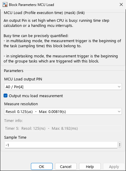
Screenshots taken with chip 33AK512MPS512
Ports
Outputs
| Port | Data Type | Description |
|---|---|---|
| L (Load) | single | CPU load measurement (enabled when “Output mcu load measurement” is checked) |
Parameters
| Parameter | Variable | Description | Options |
|---|---|---|---|
| MCU Load output PIN | MCULoadPin | GPIO pin to toggle when CPU is busy | Not Used | Any available GPIO pin |
| Output mcu load measurement | MCULoadMeasure | Enable/disable output port | on / off |
| Measure resolution | TIMER_Resolution | Timer prescaler selection | Device-dependent prescaler options |
| Timer info | Info | Read-only display of allocated timer and resolution | (read-only) |
| Sample Time | SampleTime | Block output update rate | -1 (inherited) | Positive value |
Measurement Method
The block uses a hardware timer that increments only when the MCU is busy (not idle). The timer value represents accumulated busy time within the measurement window.
Timer behavior:
- Timer runs when executing tasks or ISRs
- Timer stops when MCU enters idle loop
- Timer value read at block sample time
- Result stored in
MCHP_MCULoadResult[]array (multitasking) or reset after read (single-tasking)
GPIO pin (optional):
- Pin set high when CPU is busy
- Pin set low during idle
- Allows external measurement with oscilloscope/logic analyzer
Timer Resource Allocation
The block automatically allocates a hardware timer with these characteristics:
- Timer Type: 5 (MCU Load exclusive use)
- Timer Startup: 0 (Timer off, PR = default 65535)
- Prescaler: Selectable based on device family
Prescaler Options by Device Family
| Device Family | Available Prescalers |
|---|---|
| dsPIC30F/33F/33E/33C | 1, 8, 64, 256 |
| dsPIC33A/PIC32A | 0.5, 1, 2, 8, 32, 64, 256 |
| PIC32 (MIPS) | 1, 2, 4, 8, 16, 32, 64, 256 |
| SAMx7/PIC32CZ | 8, 32, 128 |
| SAMx2/x5 | 1, 2, 4, 8, 16, 64, 256, 1024 |
The callback calculates timer resolution based on:
Ticks = PRESCALER / FcyRef
Resolution = Ticks (per tick)
MaxPeriod = Ticks * 65536 (max measurement window)
Code Generation
TLC Implementation:
- Block type:
MCHP_MCU_LOAD - Timer initialization: Timer value set to 0 at startup (dsPIC33A/PIC32A only)
- Output: Reads
MCHP_MCULoadResult[idx]for corresponding TID and Timer - Multitasking: Result persists until next read
- Single-tasking: Result reset to 0 after each read
Generated variables:
extern volatile uint16_t MCHP_MCULoadResult[];           // Load result per TID
extern volatile uint16_t MCHP_MCULoadPreviousTimerValue[]; // Previous timer value
extern volatile unsigned int mcuFlagRecursion;           // Recursion protection flag
RTWdata fields:
MCULoadTimerRef: Allocated timer indexMCULoadPin: GPIO pin index (-1 if not used)
Parameter Visibility
The “Output mcu load measurement” checkbox controls visibility of:
- TIMER_Resolution (visible when ON)
- Info (visible when ON)
- SampleTime (visible when ON)
When unchecked, the output port is removed and timer still runs but result is not output.
Internal Parameters
Hidden parameters managed by callback:
MCULoadPin_TXT: Stores pin selection text (e.g., “A0 / Pin[17]”)TIMER_Resolution_TXT: Stores resolution text (e.g., “Resol: 0.1143(us) - Max: 7.49(ms)”)MCHP_PORT: Pin configuration string{MCU Load Pin}{MCU_Load}0:1:PortPin;MCHP_TIMER_REQUEST: Timer allocation request stringMCHP_TIMER_RESULT: Timer allocation result (timer index and period)
Related Blocks
- Tasks State - Task execution monitoring
- Scheduler Options - Scheduler configuration