MCU OVERLOAD


When to use:
When to use:
- Hard real-time deadlines must be enforced (safety-critical applications)
- Detecting task overruns needed for diagnostics or fault handling
- Triggering recovery action on deadline miss (safe state, error log)
- Profiling application to identify occasional overload conditions
- Verifying scheduler configuration before production deployment
When NOT to use:
- Soft timing requirements — occasional deadline misses acceptable
- CPU always has sufficient margin (overload never occurs)
- No action taken on overload detection — block output unused
- Prefer MCU LOAD block for general utilization monitoring
Overview
The MCU OVERLOAD block monitors the multitasking scheduler for deadline violations. It outputs a bitmask indicating which task(s) experienced overload and optionally drives a GPIO pin high when any overload occurs.
Block Dialog
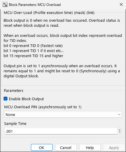
Screenshots taken with chip 33AK512MPS512
Ports
Outputs
| Port | Data Type | Description |
|---|---|---|
| (Overload Status) | uint16 | Bitmask of task overload status (bit N = TID N overload) |
Parameters
| Parameter | Variable | Description | Values |
|---|---|---|---|
| Enable Block Output | MCUOverloadBlockOutput | Enable the block output port | on / off |
| MCU Overload PIN | MCUOverLoadPin | GPIO pin set high asynchronously when overload occurs | None | Any available GPIO pin |
| Sample Time | SampleTime | Block output update rate | Any positive value (e.g., 0.001) |
Output Signal Format
The block output is a 16-bit bitmask where each bit represents the overload status of a task ID (TID):
Bit 0  → TID 0 (base rate - fastest task)
Bit 1  → TID 1
Bit 2  → TID 2
...
Bit 15 → TID 15 and higher
Reading the output clears the overload status.
GPIO Pin Behavior
When configured, the GPIO pin is set high asynchronously when any overload occurs. The pin remains high until explicitly cleared using a Digital Output block writing 0 to the same pin.
Implementation Details
Overload Detection
The block uses a volatile union containing individual bit fields for each task:
union {
  struct {
    unsigned int task0 : 1;
    unsigned int task1 : 1;
    // ... up to task15
  } b;
  unsigned int val;
} volatile MCHP_MCU_Overload;
Output Behavior
MultiTasking mode:
- Uses XOR to atomically read and clear the overload status (protection from simultaneous access)
SingleTasking mode:
- Direct read of status value, then clear to 0
Related Blocks
- MCU LOAD - CPU utilization monitoring
- Tasks State - Task execution monitoring