Tasks State


When to use:
When to use:
- Debugging multitasking behavior with oscilloscope/logic analyzer
- Visualizing task preemption and execution order externally
- Measuring actual task execution time (pulse width on GPIO pin)
- Identifying unexpected task scheduling issues (jitter, missed deadlines)
- Demonstrating real-time scheduler behavior during development
When NOT to use:
- Sufficient GPIO pins not available (one pin per task monitored)
- No external measurement tools available (scope/logic analyzer)
- Software-only profiling sufficient (use MCU LOAD block instead)
- Pin toggling overhead unacceptable (minimal but non-zero)
Overview
The Tasks State block drives GPIO pins to indicate when tasks are executing. Each task in the model can be assigned a dedicated pin that reflects its execution state, enabling external observation of task scheduling behavior.
Block Dialog
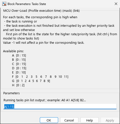
Screenshots taken with chip 33AK512MPS512
Parameters
| Parameter | Variable | Description |
|---|---|---|
| Running tasks pin list output | TasksPin | List of GPIO pins to assign to tasks, one pin per task. Use space-separated pin names (e.g., “A0 A1 A2”), range notation (e.g., “A[1:5]”), or mixed notation. |
Pin Syntax
The TasksPin parameter accepts flexible GPIO pin specifications:
- Space-separated:
A0 A1 A2assigns pins A0, A1, A2 to the first three tasks - Range notation:
A[1:5]assigns pins A1 through A5 to the first five tasks - Mixed notation:
A0 B[2:4] C1assigns A0, B2, B3, B4, C1 to tasks sequentially
Special value: -1 skips pin assignment for the corresponding task (no pin is affected for that task).
Pin Behavior
For each task, the corresponding pin is set:
- HIGH when:
- The task is running, OR
- The task execution is not finished but interrupted by a higher priority task
- LOW otherwise (task idle or completed)
The first pin in the list corresponds to the highest rate/priority task (fastest sample time). Press Ctrl+J in the model to show the task list.
Task-to-Pin Mapping
When you open the block dialog, it displays the current task list with assigned pins. Example from mask description:
Task List updated with last model build
D1 => 1 (ms) ->  pin A1
D2 => 2 (ms) ->  pin A2
D3 => 4 (ms) ->  pin A3
D4 => 4  {+1} (ms) ->  pin A4
D5 => 20 (ms) ->  pin A5
The block also lists available pins by port:
Available pins:
         A  [0   1   2   3   4   5   6   7   9  10  14  15]
         B  [0 : 15]
         C  [1   2   3   4  12  13  14  15]
         D  [0 : 15]
         E  [0 : 9]
         F  [0   1   2   3   4   5   8  12  13]
         G  [0   1   2   3   6   7   8   9  12  13  14  15]
(Available pins depend on the selected device and peripheral configuration.)
Implementation Notes
- The block configures pins as digital outputs through the
MCHP_PORTmechanism - Each valid pin is registered as
{Task D<n> Running}{Task D<n>}15:1:<pin> - Pin values of
-1are filtered out and do not affect any GPIO pin - Pin assignments are stored in the block’s
RTWdata.TaskPinProfilefor code generation
Troubleshooting
| Problem | Cause | Solution |
|---|---|---|
| Pin conflicts with other blocks | Pin already assigned to peripheral | Choose different pins or disable conflicting peripheral |
| No signal on pin | Pin not available on device | Check block dialog for list of available pins |
| Unexpected pin behavior | Pin used by analog peripheral | Verify pin is configured as digital I/O |
Related Blocks
- MCU LOAD - CPU utilization monitoring
- MCU OVERLOAD - Overload detection