Board Templates
Overview
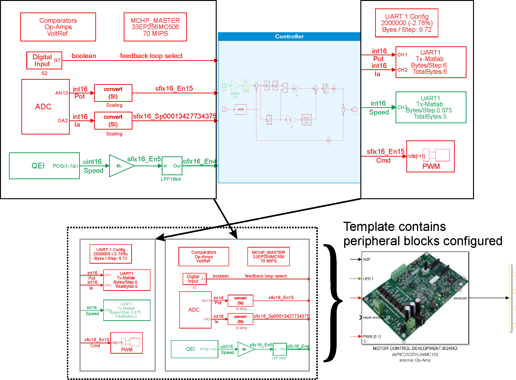
Board templates provide pre-configured Simulink models optimized for popular Microchip development boards. These templates include:
- Pre-configured Master block with correct chip selection and clock settings
- Peripheral blocks configured for board-specific hardware (PWM, ADC, UART, QEI, etc.)
- Pin assignments matching the physical board layout
- Example algorithms demonstrating typical use cases (motor control, sensor interfaces)
- Validated configurations tested on actual hardware
Why Use Board Templates?
| Benefit | Description |
|---|---|
| Fast Prototyping | Start coding control algorithms in minutes instead of hours spent on peripheral configuration |
| Validated Hardware | All pin assignments and peripheral settings verified on actual hardware - reduces debugging time |
| Best Practices | Templates follow Microchip recommended configurations for optimal performance |
| Learning Tool | Study working examples to understand peripheral configuration patterns |
| Easy Portability | Switch between boards by simply loading a different template - same algorithm, different hardware |
Available Board Templates
MCLV-2 (Motor Control Low Voltage)
Target Applications: Low-voltage motor control, BLDC/PMSM development
Key Features:
- 24V max, 8A continuous motor drive
- Integrated current sensing with op-amps
- QEI encoder interface
- Push buttons and LEDs for user interface
- Compatible with dsPIC33E, 33C, 33A families
Template Models: FOC control, six-step commutation, sensor interfaces
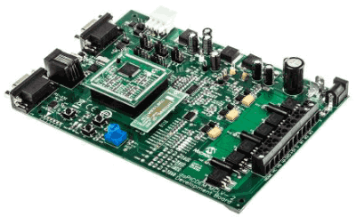
LVMC (Low Voltage Motor Control)
Target Applications: Entry-level motor control prototyping
Key Features:
- Compact form factor
- Integrated H-bridge driver
- On-board current sensing
- Plug-in module (PIM) socket for easy chip swapping
- USB programmer interface
Template Models: Basic PWM control, ADC sampling, UART communication
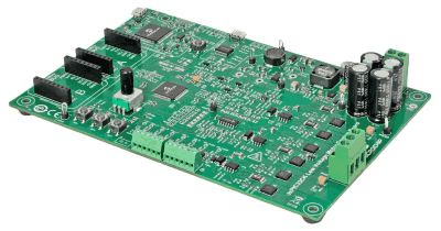
MCLV 300W-48V
Target Applications: Higher power motor control, industrial applications
Key Features:
- 48V DC bus, 300W continuous power
- Optimized for dsPIC33A (32-bit DSC with FPU)
- Three-phase current sensing
- High-speed PWM with dead-time control
- CAN communication interface
Template Models: Advanced FOC, floating-point control, high-resolution PWM
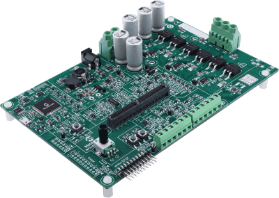
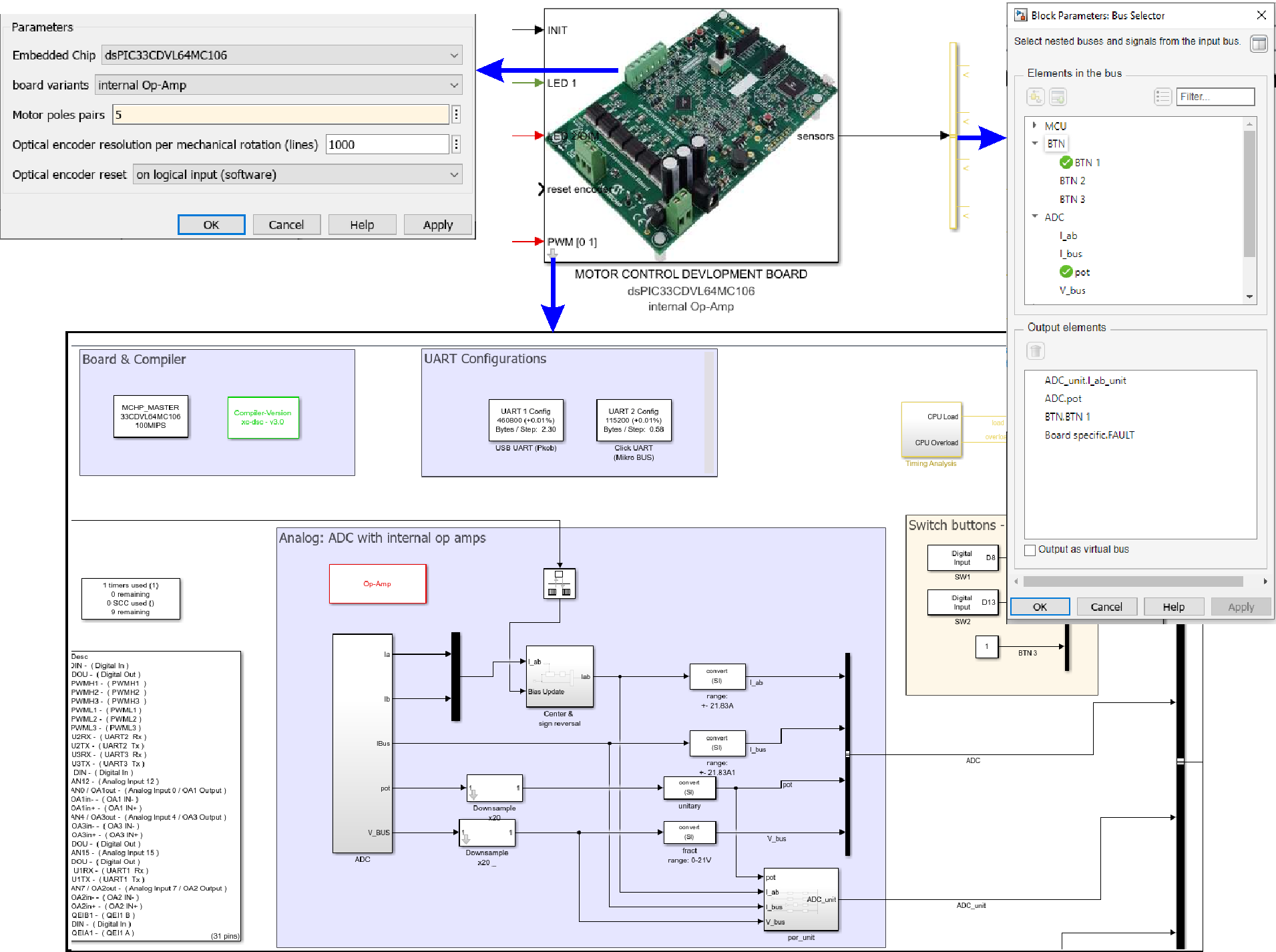
Motor Control Dev Board (33CDV64MC106)
Target Applications: Dual-core motor control applications
Key Features:
- dsPIC33CDV dual-core architecture
- Independent PWM modules per core
- Multi-motor control capability
- Integrated communication peripherals
- Flexible I/O configuration
Template Models: Dual-motor control, master-slave coordination

Curiosity Nano (EV17P63A) — dsPIC33AK512MPS506
Target Applications: Power supply control, DC-DC converters, digital power management
Key Features:
- Compact nano form factor (breadboard-compatible)
- dsPIC33AK512MPS506 (32-bit DSC with FPU)
- High-resolution PWM (78 ps Fine Edge Placement)
- 4 PWM generators optimized for power electronics
- 3 ADC cores (40 MSPS) with 25 input channels
- On-board debugger with USB-UART bridge (no external programmer needed)
- USB-C power and programming
- Multiple communication interfaces (CAN, I2C, SPI, UART)
Template Models: Digital power supply control, DC-DC converter PWM, multi-phase power management
How to Use Board Templates
Method 1: Creating New Model from Template
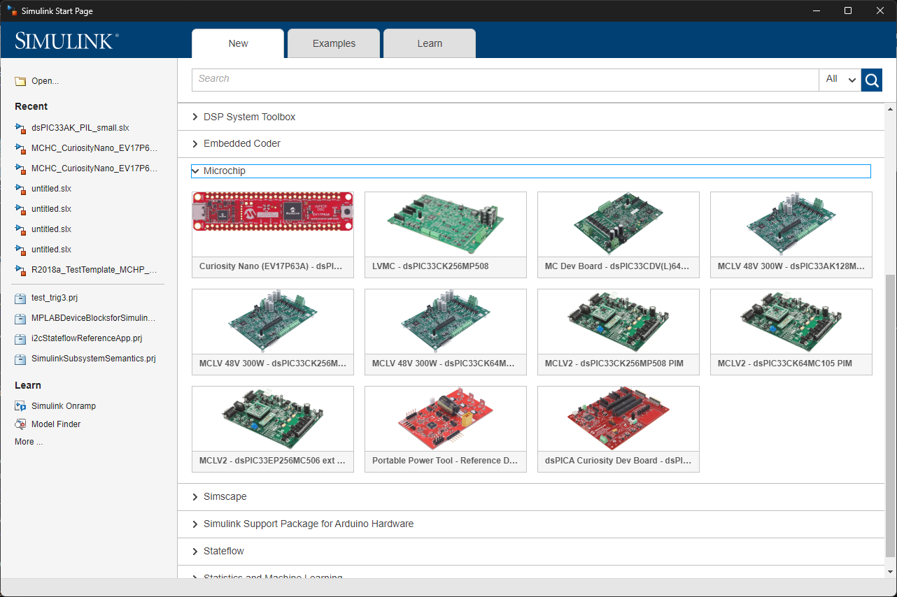
- Open Simulink: Launch MATLAB and open the Simulink Start Page
- Browse Templates: Navigate to Simulink Start Page → Templates → Microchip
- Select Board: Choose your target development board from the list
- Create Model: Click “Create Model” to generate a new model with pre-configured peripherals
- Customize Algorithm: Replace the placeholder algorithm with your control logic
- Build: Click the Build button (Ctrl+B) to generate code and program the board
Method 2: Loading Template Example
- In MATLAB command window, type:
mchpto open the block library - Navigate to MCHP Blockset → Examples → [Board Name]
- Double-click the desired example model
- Study the configuration and modify as needed
- Save as new model for your project
Template Structure
A typical board template includes the following components:
1. Master Block Configuration
- Target Device: Pre-selected chip matching the board (e.g., dsPIC33CK256MP508)
- Clock Configuration: Oscillator settings for maximum performance
- Compiler Settings: Optimization level, memory model, code replacement
- Programmer Selection: ICD4/ICD5/PICkit configuration
2. Peripheral Blocks
Templates include commonly-used peripherals pre-configured for the board hardware:
| Peripheral | Typical Configuration | Purpose |
|---|---|---|
| PWM | Center-aligned, complementary outputs with dead-time | Motor drive, power conversion |
| ADC | Synchronized with PWM, parallel sampling, multiple channels | Current/voltage sensing |
| QEI | Quadrature decoding with index, configurable resolution | Motor position/speed measurement |
| UART | 115200 baud (upgradeable to 2Mbaud with FTDI) | Data logging, parameter tuning (picgui) |
| Digital I/O | Buttons (input), LEDs (output), fault signals | User interface, status indication |
| Op-Amps | Configured for current sensing with appropriate gain | Analog signal conditioning |
3. Sample Algorithm
Templates include a working control algorithm demonstrating:
- Multi-rate execution (fast current loop, slower speed loop)
- Proper scaling and fixed-point data types
- Real-time constraint management
- Best practices for embedded code generation
4. Visualization & Debug Tools
- Task State blocks: Monitor task execution on scope/LEDs
- MCU Load block: Measure CPU utilization
- UART Tx-Matlab: Stream data to picgui for real-time plotting
- Scope trigger points: Pre-configured measurement points
Switching Between Boards
One of the key advantages of templates is easy portability. To migrate an algorithm from one board to another:
- Save Current Model: Backup your algorithm implementation
- Extract Algorithm: Copy your control algorithm subsystem (without peripheral blocks)
- Open Target Template: Load the template for your new target board
- Paste Algorithm: Insert your control algorithm into the new template
- Verify Connections: Ensure algorithm inputs/outputs connect to peripheral blocks
- Adjust Parameters: Update scaling factors, sample times if board specs differ
- Build & Test: Compile for new target and verify functionality
Example: Moving a FOC algorithm from MCLV-2 (dsPIC33CK) to MCLV-300W48V (dsPIC33A) requires only:
        Updating current sensor scaling (different op-amp gains)
        Adjusting PWM frequency (different board power stage limits)
        Optionally switching from fixed-point to floating-point (utilizing dsPIC33A's FPU)

    The core control algorithm remains unchanged!
Template Customization
Common Customization Tasks
| Task | Steps |
|---|---|
| Change PWM Frequency | Double-click PWM block |
| Add ADC Channel | Double-click ADC block |
| Enable CAN Communication | Add “CAN Config” block from MCHP library |
| Change Clock Speed | Double-click Master block |
Advanced Customization
- Multi-rate Scheduling: Add subsystems with different sample times to implement multi-tasking
- Fixed-Point Optimization: Use Fixed-Point Tool to convert floating-point to fixed-point for faster execution
- Code Replacement: Enable hardware-optimized functions in Configuration Parameters → Code Generation
- External Mode: Add XCP-on-Serial support for real-time parameter tuning from Simulink
- PIL Testing: Configure Processor-in-the-Loop to verify generated code behavior
Template Best Practices
Best Practices:
- Start with Template: Always begin with a board template rather than blank model - saves configuration time
- Preserve Original: Save template-based models with new names to keep clean templates available
- Match Time Steps: Ensure Simulink base time step matches PWM period (if using PWM-triggered ADC)
- Verify Pin Assignments: Check physical board pinout matches template configuration before hardware testing
- Test Incrementally: Start with simple algorithm, verify peripherals work, then add complexity
- Use Task State Blocks: Monitor real-time execution with Task State and MCU Load blocks
- Document Changes: Add comments to model explaining customizations from original template
Troubleshooting Template Issues
Model Won’t Build
- Compiler Path: Verify compiler installation in Configuration Parameters → Code Generation → System target file
- MATLAB Version: Ensure MATLAB version matches template requirements (R2020b+ recommended)
- Toolbox Dependencies: Check Embedded Coder, MATLAB Coder, Simulink Coder installed
- Path Issues: Run
rehash toolboxcacheif blockset not found
Hardware Not Responding
- Programmer Connection: Verify ICD/PICkit connected and powered
- Board Power: Ensure development board has power supply connected
- Chip Selection: Verify Master block targets correct chip for your board version
- Fuse Settings: Check configuration bits match hardware (oscillator type, debug pins)
Incorrect Peripheral Behavior
- Pin Mismatch: Verify template pin assignments match your board revision
- Scaling Errors: Check ADC/PWM scaling factors match your hardware (sensor gains, voltage levels)
- Timing Issues: Verify sample times and peripheral frequencies are correctly configured
- Real-time Violations: Use MCU Load block to check for overload conditions
Creating Custom Templates
Once you’ve configured a model for a custom board, you can save it as a template for reuse:
- Configure Model: Set up all peripherals and verify working on hardware
- Clean Algorithm: Replace specific control logic with generic placeholder algorithm
- Add Documentation: Include block comments explaining peripheral configuration
- Create Template File: Save as .sltx template file (File → Save As → Simulink Template)
- Add Metadata: Fill in template description, tags, and preview image
- Share: Distribute template to team or organization
Custom Board Note: When creating templates for custom hardware, thoroughly document:
        Pin assignments and their mapping to board connectors
        Clock configuration rationale and limitations
        Scaling factors for analog inputs (sensor gains, voltage dividers)
        Known hardware limitations or errata workarounds
Example Use Case: DC Motor Control
Using the MCLV-2 template, you can implement a cascaded PI controller for DC motor speed control in under 30 minutes:
Load Template: Open “MCLV2_dsPIC33CK_MotorControl_Template”
Pre-configured Peripherals:
PWM: 20kHz, center-aligned, 1µs dead-time
ADC: Synchronized to PWM, measuring motor current (AN0) and potentiometer (AN13)
QEI: 1000-line encoder, speed measurement at 2ms rate
UART: 115200 baud for picgui data logging
Add Control Algorithm:
Inner current loop: PI controller at 50µs (20kHz)
Outer speed loop: PI controller at 1ms (1kHz)
Speed reference from potentiometer
Build & Deploy: Press Ctrl+B to generate code and program board
Tune & Visualize: Use picgui to monitor speed/current in real-time and adjust PI gains
Result: Working motor control system in 30 minutes instead of several hours of manual configuration!
See Also
[MCHP Blockset Overview] | [Quick Start Guide] | [Motor Control Examples] | [External Mode & PIL] | User Guide