MCHP Blockset Overview
Overview
The MCHP Blockset enables Model-Based Design for Microchip microcontrollers, providing a comprehensive library of peripheral blocks for embedded code generation from Simulink models.
Key Features
- Automatic C Code Generation - Generate optimized embedded C code for dsPIC, PIC32, and SAM devices
- Comprehensive Peripheral Library - PWM, ADC, UART, SPI, I2C, CAN, Timers, and more
- External Mode - Real-time parameter tuning and signal monitoring
- Processor-in-the-Loop (PIL) - Validate generated code on actual hardware
- Hardware Optimizations - Assembly code replacement for dsPIC families
- Multitasking Scheduler - Rate monotonic scheduler for multi-rate applications
Supported Device Families
| Family | Architecture | Series | Typical Applications |
|---|---|---|---|
| dsPIC33A | 32-bit DSC with FPU | 33AK | Advanced Motor Control, Digital Power, Floating-Point DSP |
| dsPIC | 16-bit DSC | 30F, 33F, 33E, 33CH, 33CK, 33CDV | Motor Control, Power Conversion, Digital Power |
| PIC32 | 32-bit MCU | MK, MZ, MX | IoT, Industrial Control, Audio Processing |
| SAM | ARM Cortex-M | E5x, E7x, C2x, D2x | Industrial Automation, Motor Control |
Model-Based Design Workflow
The MCHP Blockset implements a complete Model-Based Design (MBD) workflow, enabling seamless transition from algorithm simulation to embedded code execution. The workflow follows three main phases:

1. Simulation Phase
Develop and validate your control algorithm in the Simulink environment:
- Plant Modeling - Create mathematical models of your physical system (motor, power converter, etc.)
- Controller Design - Implement control algorithms using standard Simulink blocks
- Closed-Loop Simulation - Test controller performance with simulated plant dynamics
- Parameter Tuning - Optimize gains and parameters in fast simulation cycles
2. Code Generation Phase
Transform your validated algorithm into embedded C code:
- Add Peripheral Blocks - Replace simulated inputs/outputs with MCHP hardware blocks (ADC, PWM, UART, etc.)
- Configure Target - Select Microchip device, set clock frequency, choose compiler
- Automatic Code Generation - Embedded Coder generates optimized C code including peripheral drivers and scheduler
- One-Click Build - Press “Build” button to compile and program your hardware
3. Verification & Testing Phase
Validate that your embedded implementation matches simulation expectations:
- Hardware Testing - Run algorithm on actual microcontroller with real sensors/actuators
- External Mode - Monitor signals and tune parameters in real-time using XCP protocol
- Processor-in-the-Loop (PIL) - Compare simulation results with actual execution on target hardware
- Timing Analysis - Measure CPU load and verify real-time constraints are met
- Data Logging - Stream runtime data to MATLAB for analysis using picgui interface
Typical Development Steps
- Start from Template - Load pre-configured board template (see [Board Templates])
- Model Design - Create or import control algorithm in Simulink
- Add Peripherals - Drag and drop MCHP blocks for hardware interfaces (PWM, ADC, UART, etc.)
- Configure Target - Select device, set clock, configure peripherals
- Simulate - Verify algorithm behavior in simulation with plant model
- Generate Code - Automatic C code generation with Embedded Coder
- Build & Deploy - Compile and program target device (single button press)
- Test & Tune - Use External Mode or picgui for real-time optimization
- Validate - Run PIL tests to verify numerical accuracy and timing performance
MCHP Block Library
The blockset provides a comprehensive library of peripheral blocks for Microchip microcontrollers, enabling graphical configuration of hardware resources without writing driver code:
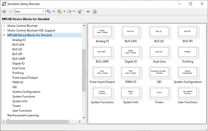
The library includes blocks for all major peripheral categories:
| Category | Blocks | Purpose |
|---|---|---|
| System | Master, Clock Configuration, MCU Load, Task State | Chip selection, timing configuration, performance monitoring |
| PWM | High-Speed PWM, PWM with FEP, Standard PWM, MC PWM | Motor drive, power conversion, precise waveform generation |
| ADC | High-Speed 12-bit, SAR ADC, Standard ADC, AFEC | Analog-to-digital conversion for sensors and measurements |
| Communication | UART, SPI, I2C, CAN | Serial communication with peripherals and host systems |
| Encoders | QEI, PDEC, Hall Sensors | Motor position and speed measurement |
| Digital I/O | Digital Input, Digital Output, Change Notification | GPIO control, button inputs, LED outputs |
| Timers | Timer, Timer Input Capture, Timer Output Compare | Periodic interrupts, event capture, pulse generation |
| Analog | DAC, Op-Amp, Comparator, Voltage Reference | Analog output, signal conditioning, threshold detection |
| Utility | Data Visualization (picgui), External Mode, PIL | Real-time debugging, parameter tuning, code verification |
Target Applications
- Motor Control - FOC, BLDC, PMSM, Stepper motors
- Power Conversion - SMPS, PFC, DC-DC converters, inverters
- Digital Power - Advanced control loops, adaptive algorithms
- Signal Processing - Filters, FFT, sensor fusion
- Communication - CAN, LIN, Ethernet, USB
See Also
[Installation] | [Quick Start Guide] | [Board Templates] | [Supported Devices] | [External Mode & PIL] | User Guide